Unlock instant, AI-driven research and patent intelligence for your innovation.

Sensor module

a sensor module and sensor technology, applied in the field of sensors, can solve the problems of low mechanical strength and thermal fatigue resistance, insufficient reliability as a solder for electronic devices, and solder deterioration

Pending Publication Date: 2022-08-25
SEIKO EPSON CORP
View PDF8 Cites 0 Cited by
  • Summary
  • Abstract
  • Description
  • Claims
  • Application Information

AI Technical Summary

Benefits of technology

The invention is a sensor module that includes a substrate and two terminals on its surface, a lead, a first conductive bonding member, an inertial sensor, and a second conductive bonding member. The lead is connected to the first terminal, and the first conductive bonding member bonds the lead and the first terminal together. The inertial sensor is attached to the second terminal, and the second conductive bonding member bonds the inertial sensor and the second terminal together. The technical effect of this invention is to provide a reliable and reliable connection between the lead and the terminals, as well as between the inertial sensor and the terminals.

Problems solved by technology

Unfortunately, in the electronic device described in JP-A-10-242633, as a solder material having a lower melting temperature, for example, a Sn—Bi eutectic solder is used, which has low mechanical strength and thermal fatigue resistance and is not sufficient in reliability as a solder for the electronic device.
For this reason, when the solders in the electronic device described in JP-A-10-242633 are selectively used and applied to, for example, a sensor module in which an inertial sensor such as an acceleration sensor or an angular velocity sensor is mounted at a substrate, there is a problem that in an environment for using the sensor module, a stress caused by a difference in thermal expansion coefficients of the inertial sensor and the substrate is repeatedly applied to the solder as a bonding portion between the inertial sensor and the substrate, and thus the solder deteriorates and the sensor module becomes unstable in function and decreased in reliability.

Method used


Image

  • Sensor module
  • Sensor module
  • Sensor module

Examples


first embodiment

1. First Embodiment

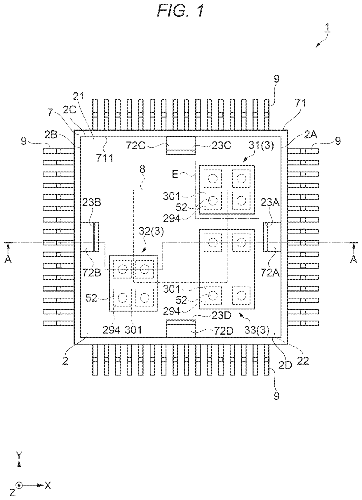
[0019]A sensor module 1 according to the first embodiment will be described with reference to FIGS. 1 to 4. FIG. 1 illustrates a state in which a top plate 70 of a cap 7 is removed for convenience of describing an internal configuration of the sensor module 1. In FIG. 4, for convenience of describing an internal configuration of a first inertial sensor 31, components other than an acceleration sensor element 310, an angular velocity sensor element 3r, and internal electrodes 313 are omitted. Dimensional ratios of each component in each drawing are different from actual dimension ratios.

[0020]As to coordinates illustrated in the drawings, three axes orthogonal to each other are referred to as an X axis, a Y axis, and a Z axis. A direction along the X axis is defined as an “X direction”, a direction along the Y axis is defined as a “Y direction”, and a direction along the Z axis is defined as a “Z direction”, in each of which a direction indicated by an arrow is a p...

second embodiment

2. Second Embodiment

[0095]Next, a sensor module 1a according to the second embodiment will be described with reference to FIGS. 10 and 11. In the following description, differences from the first embodiment described above will be mainly described, the same reference numerals are given to the same configuration as the first embodiment, and redundant description will be omitted.

[0096]The sensor module 1a according to the present embodiment is different from the first embodiment in that the first surface 21 of the substrate 2 is provided with first terminals 292a.

[0097]As shown in FIG. 10, the first terminals 292a are provided at the first surface 21 as the upper surface of the substrate 2, and each first terminal 292a and each coupling portion 91a of a lead 9a overlap each other when viewed from the top in the Z direction.

[0098]As shown in FIG. 11, the first terminals 292a provided at the first surface 21 of the substrate 2 are bonded to the coupling portions 91a of the lead 9a via ...

third embodiment

3. Third Embodiment

[0102]Next, a sensor module 1b according to the third embodiment will be described with reference to FIGS. 12 and 13. In the following description, differences from the first embodiment described above will be mainly described, the same reference numerals are given to the same configuration as the first embodiment, and redundant description will be omitted.

[0103]The sensor module 1b according to the present embodiment is different from the first embodiment in that the inertial sensor 3 is bonded to the substrate 2 via an insulating bonding member 60. The present embodiment is also different from the first embodiment in that the circuit element 8 is bonded to the substrate 2 via an insulating bonding member 61.

[0104]As shown in FIG. 12, when viewed from the top in the Z direction, the insulating bonding member 60 is disposed at a central portion of the lower surface of the inertial sensor 3. As shown in FIG. 13, the lower surface of the inertial sensor 3 is bonded ...


PUM


Abstract

A sensor module includes: a substrate including a first terminal and a second terminal; a first conductive bonding member having a first melting point and a first Young's modulus; a lead bonded to the first terminal by the first conductive bonding member; a second conductive bonding member having a second melting point lower than the first melting point and a second Young's modulus higher than the first Young's modulus; and an inertial sensor bonded to the second terminal by the second conductive bonding member.

Description

[0001]The present application is based on, and claims priority from JP Application Serial Number 2021-028264, filed Feb. 25, 2021, the disclosure of which is hereby incorporated by reference herein in its entirety.BACKGROUND1. Technical Field[0002]The present disclosure relates to a sensor module.2. Related Art[0003]In related art, as described in JP-A-10-242633, it is known that when an electronic device is manufactured by soldering and fixing, to a substrate, an electronic component such as a piezoelectric element in which a piezoelectric element piece is fixed in an airtight package, a solder having a high melting temperature is used in a previous operation of soldering and fixing, and a solder having a low melting temperature is used in a subsequent operation of soldering and fixing, so that the subsequent soldering does not affect the previous soldering due to different melting temperatures of solders.[0004]Unfortunately, in the electronic device described in JP-A-10-242633, as...

Claims


Application Information

Patent Timeline
IPC IPC(8): G01P15/08B81B7/00G01P15/18G01P3/00
CPCG01P15/08B81B7/007G01P15/18G01P3/00B81B2201/0228B81B2207/012G01C21/16B81B2207/017B81B2201/0242B81C2203/035G01P15/0802G01P1/023
Inventor SAKUMA, MASAYASU
Owner SEIKO EPSON CORP