
Method for producing a part from composite material by injecting a filled slip into a fibrous texture

a composite material and filling technology, applied in the direction of ceramic shaping apparatus, manufacturing tools, discharging arrangement, etc., can solve the problems of the blank catching on the mould, the risk of deformation and/or damage of the blank and/or the mould during the demoulding operation, and the delicate operation of the blank after the injection and filtration of the filling slip

Pending Publication Date: 2022-09-08
SN DETUDE & DE CONSTR DE MOTEURS DAVIATION S N E C M A
View PDF0 Cites 0 Cited by
  • Summary
  • Abstract
  • Description
  • Claims
  • Application Information

AI Technical Summary

Benefits of technology

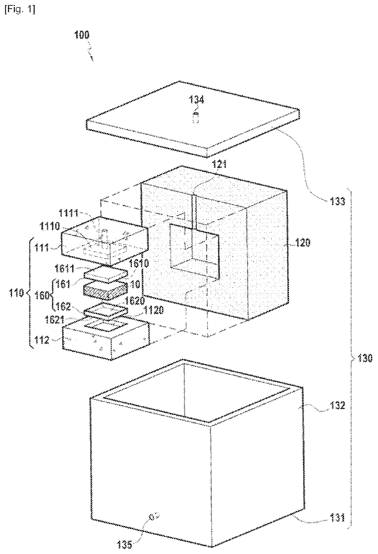
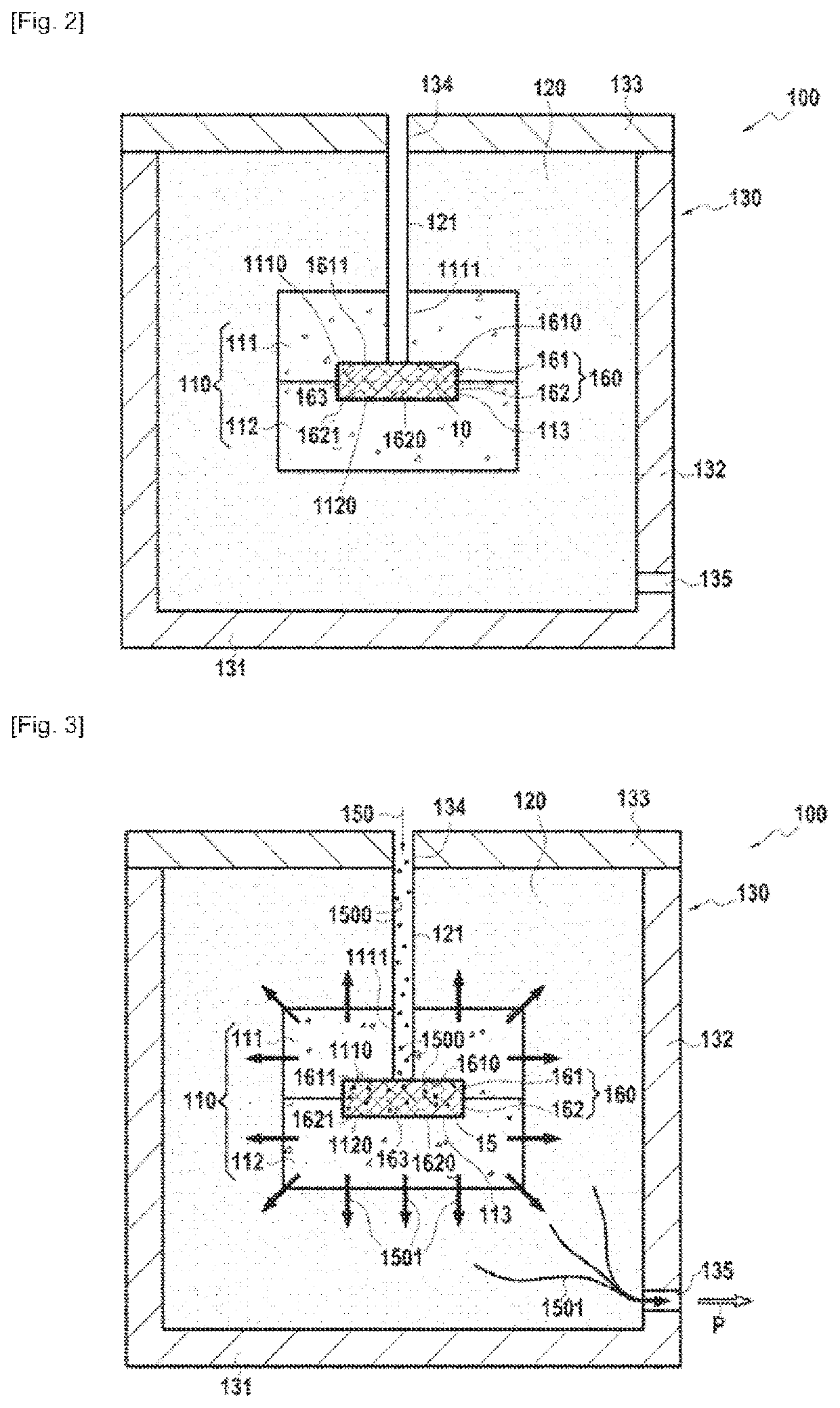
The present invention aims to minimize the risk of damage and deformation to parts during demolding after injection and filtration of a filled slip into the mold. The solution involves the use of a sacrificial capsule which avoids mechanical demuseppeing force on the blank, ensuring that the blank retains its integrity and shape after demolding. This also reduces the risk of damaging the porous material mold.

Problems solved by technology

While this solution makes it possible to optimize the drainage of the liquid phase from the slip and to deposit the particles in the moulding cavity in a homogeneous and dense manner, the demoulding of the blank after injection and filtration of the slip is a delicate operation.
Indeed, the roughness of the porous material mould combined with the submicron size of the powders deposited during the injection of the slip into the moulding cavity cause the blank to catch on the mould.
Since the blank is demoulded by a mechanical force (lever, scraping, etc.), there is a significant risk of deforming and / or damaging the blank and / or the mould during the demoulding operation.
The application of a mechanical demoulding force on the blank can, in particular, cause local tears and / or cracks therein.

Method used


Image

  • Method for producing a part from composite material by injecting a filled slip into a fibrous texture
  • Method for producing a part from composite material by injecting a filled slip into a fibrous texture

Examples


Embodiment Construction

[0030]The invention generally applies to the manufacture of parts created by injection of a particle-filled slip into a mould able to drain or filter the liquid phase of the slip so as to retain the particles that then constitute all or a portion of the part. In a non-limiting manner, the tooling of the invention can be used to manufacture single-piece ceramic parts, parts or coatings of abradable material and parts of thermostructural composite material, especially of the oxide / oxide type or with a ceramic matrix (CMC).

[0031]We will now describe a manufacturing method of the invention applied to the manufacture of a composite material part of the oxide / oxide or CMC type. The method for manufacturing a composite material part, especially of the oxide / oxide or CMC type, according to the present invention starts by creating a fibrous texture intended to form the reinforcement for the part.

[0032]The method for manufacturing a composite material part, especially of the oxide / oxide or CM...


PUM

PropertyMeasurementUnit
Temperatureaaaaaaaaaa

Abstract

A manufacturing method for a composite material part includes injecting under pressure a slip containing a refractory ceramic particle powder into the moulding cavity of an injection tooling, draining the liquid from the slip that passed through the moulding cavity and retaining the particle powder inside the moulding cavity to obtain a blank including refractory particles, demoulding the blank, and heat treating the blank to form a part. The injection tooling includes a porous material mould consisting of a moulding cavity, an enclosure of rigid material in which the porous material mould is held, the enclosure further including an injection port, a discharge vent and an injection canal connecting the injection port to the moulding cavity of the porous mould for the injection of the slip into the moulding cavity. The injection tooling includes a sacrificial capsule of porous material placed in moulding cavity.

Description

TECHNICAL FIELD[0001]The present invention concerns the manufacture of parts from a particle-filled slip and especially ceramic parts, of abradable material or thermostructural composite material especially of the oxide / oxide type or a ceramic matrix (CMC), i.e., having a fibrous reinforcement formed of refractory ceramic fibres densified by a matrix also of refractory ceramic material.PRIOR ART[0002]In the case of parts of oxide / oxide composite material, or CMC, these can be created by a liquid process that comprises a step of impregnating a fibrous texture with a filled slip, for example with alumina particles in the case of an oxide / oxide composite material or silicon carbide (SiC) particles in the case of a CMC composite material. In such a case, it is necessary to drain or filter the liquid phase from the slip in order to obtain optimal filling of the residual porosities present in the fibrous texture with the solid fillers.[0003]Document WO 2017 / 060601 describes the use of a p...

Claims


Application Information

Patent Timeline
IPC IPC(8): B28B1/26B28B1/24C04B35/80C04B35/64C04B35/628
CPCB28B1/261B28B1/24C04B35/80C04B35/64C04B35/62844C04B35/62892C04B2235/5252C04B2235/6022C04B2235/6027C04B2235/616C04B2235/661C04B2235/6562C04B2235/6567B28B1/26B28B1/262B28B13/06B28B11/243C04B35/66C04B35/638C04B2235/5216C04B2235/5256B28B7/342B28B7/348B28B23/0006C04B41/0072C04B2235/5224C04B2235/5228C04B2235/5232C04B35/117C04B35/6263C04B35/185C04B35/14C04B35/18C04B35/447C04B2235/606C04B2235/5244C04B2235/5248C04B35/565C04B35/58071C04B35/584
Inventor DROZ, NICOLASIGLESIAS CANO, CÉLIALE BIEZ, PHILIPPE CHARLES ALAINLIAIS, LUDOVIC PHILIPPE
Owner SN DETUDE & DE CONSTR DE MOTEURS DAVIATION S N E C M A
Learn More