
Woodworking vise

Active Publication Date: 2022-09-15
HANGZHOU UNITED TOOLS CO LTD +1
View PDF5 Cites 0 Cited by
  • Summary
  • Abstract
  • Description
  • Claims
  • Application Information

AI Technical Summary

Benefits of technology

The present invention relates to a woodworking vise with a movable jaw that can be fixed in a straight line direction after clamping by a clamping surface. The vise includes a vise body with a longitudinal axis, a first jaw and a second jaw movably connected to the vise body along its length. The movable jaw has a force applying means with a camshaft and a locking block. The force applying means can be fixed to the camshaft and the locking block can be slidably connected to the vise body. The vise also includes a woodworking vise with a movable jaw that can be fixed in a straight line direction after clamping by a clamping surface. The technical effects of this invention include improved accuracy and efficiency in woodworking operations.

Problems solved by technology

In view of the above described shortcomings of the prior art, the technical problem to be addressed by the present application is the existence of the technical problem of a deviation from a straight line direction of guide rails after clamping by clamping surfaces.

Method used


Image

  • Woodworking vise
  • Woodworking vise
  • Woodworking vise

Examples


Embodiment Construction

[0058]Below, the drawings accompanying this specification are referenced to introduce many preferred embodiments of the present application so that the techniques disclosed herein become more apparent and better understood. The present application may be embodied in many different forms of embodiment, and the protection scope of the present application is not limited only to the embodiments mentioned herein.

[0059]Throughout the accompanying drawings, structurally identical parts are indicated with identical reference numerals, and structurally or functionally similar components are indicated with similar reference numerals. The size and thickness of each component in the drawings are arbitrarily depicted, and the present application is not limited to any size or thickness of each component. For greater clarity of illustration, the thicknesses of some parts are exaggerated as appropriate somewhere in the drawings.

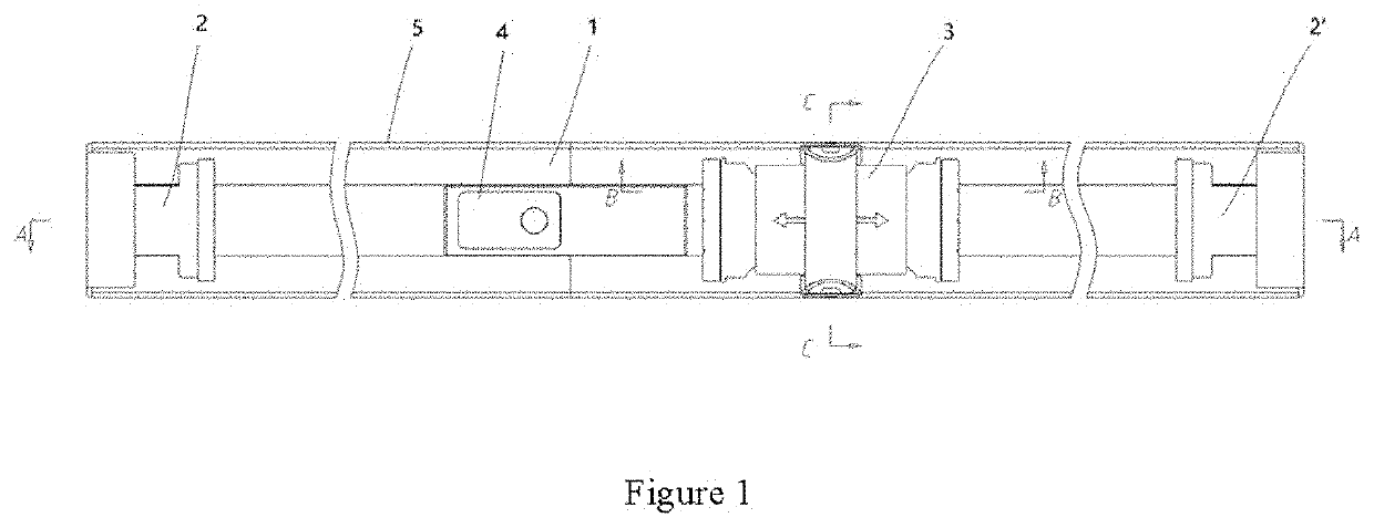
[0060]As shown in FIG. 1, a schematic diagram showing the structure of ...


PUM


Abstract

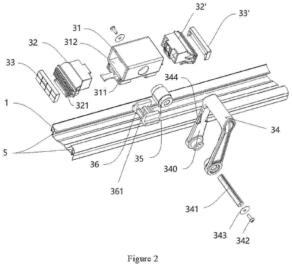
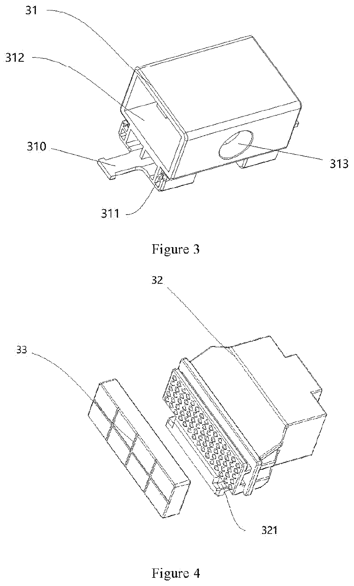
A woodworking vise includes a profiled vise body (1), a first jaw (2) and a second jaw (2′). The first jaw (2) and the second jaw (2′) are disposed at both ends of the vise body along its longitudinal axis. The woodworking vise further includes at least one movable jaw (3). The at least one movable jaw (3) is slidably connected to a top surface of the profiled vise body. Between the movable jaw (3) and the top surface of the profiled vise body (1), a locking block (36) is disposed, and a bottom surface of the locking block (36) is slidably connected to the top surface of the profiled vise body (1). The movable jaw (3) includes a force applying means (34) and a camshaft (35). The camshaft (35) has at least one cam, and the force applying means (34) is connected to the camshaft (35). Moreover, the force applying means (34) is able to rotate about a center axis of the camshaft (35) to drive the camshaft (35) to rotate therewith to cause the cam of the camshaft (35) to press against the locking block (36) and, by means of the locking block (36), press and secure the movable jaw (3) against and to the top surface of the vise body (1). Wherein, the center axis of the camshaft (35) is perpendicular to the longitudinal axis of the profiled vise body (1). This woodworking vise can solve the problem of an angle of clamping deviation.

Description

FIELD OF THE INVENTION[0001]This application relates to the technical field of vises and, in particular, to a woodworking vise.DESCRIPTION OF THE PRIOR ART[0002]Woodworking vises are commonly used clamping devices on workbenches for fixing workpieces to facilitate their processing. For workpiece of different lengths, vises of different sizes are typically used.[0003]In the prior art, there is a vise capable of adjusting its clamping length. For example, as shown in the patent CN208744613, the vise includes a vise body, a fixed jaw fixed to the vise body, and a movable jaw assembly movably connected to the vise body and movable along the vise body. The vise body is made up of at least two vise body segments that are put together. The vise body segments that are put together are connected by a vise body connecting means. The vise body is made up of at least two vise body segments that are put together, and the vise body segments, after being put together, can extend an overall length ...

Claims


Application Information

Patent Timeline
IPC IPC(8): B25B1/08B25B1/02B25B1/24
CPCB25B1/08B25B1/02B25B1/2489B27C9/00
Inventor LI, YUEMING
Owner HANGZHOU UNITED TOOLS CO LTD
Learn More