Cooking appliance with elevating platform

Pending Publication Date: 2022-09-15
HAIER US APPLIANCE SOLUTIONS INC
View PDF0 Cites 0 Cited by
  • Summary
  • Abstract
  • Description
  • Claims
  • Application Information

AI Technical Summary

Benefits of technology

The invention is a cooking appliance with two configurations: one with a vertical inner shell and an upper heating module, and another with a lateral inner shell and a movable platform that can move between a bottom position and an elevated position. The technical effects of this design include improved cooking efficiency, precise control of cooking temperatures, and improved user experience.

Problems solved by technology

However, in some instances, and in particular when heating relatively small portions or amounts of food, the food items may be positioned away from one of the heat sources such that heat energy from the heat source takes too long to reach the food, and a significant portion of the heat energy may be lost or dissipated before reaching the food, resulting in longer cooking times and less efficient energy use.

Method used


Image

  • Cooking appliance with elevating platform
  • Cooking appliance with elevating platform
  • Cooking appliance with elevating platform

Examples


Embodiment Construction

[0018]Reference now will be made in detail to embodiments of the invention, one or more examples of which are illustrated in the drawings. Each example is provided by way of explanation of the invention, not limitation of the invention. In fact, it will be apparent to those skilled in the art that various modifications and variations can be made in the present invention without departing from the scope of the invention. For instance, features illustrated or described as part of one embodiment can be used with another embodiment to yield a still further embodiment. Thus, it is intended that the present invention covers such modifications and variations as come within the scope of the appended claims and their equivalents. As used herein, the term “or” is generally intended to be inclusive (i.e., “A or B” is intended to mean “A or B or both”). The terms “first,”“second,” and “third” may be used interchangeably to distinguish one component from another and are not intended to signify l...


PUM


Abstract

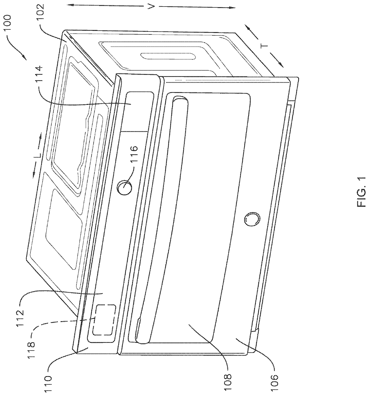
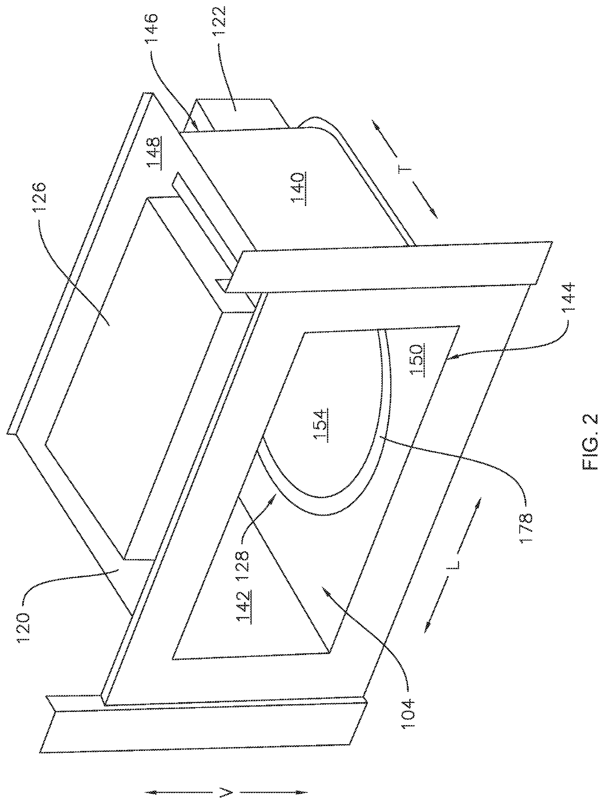
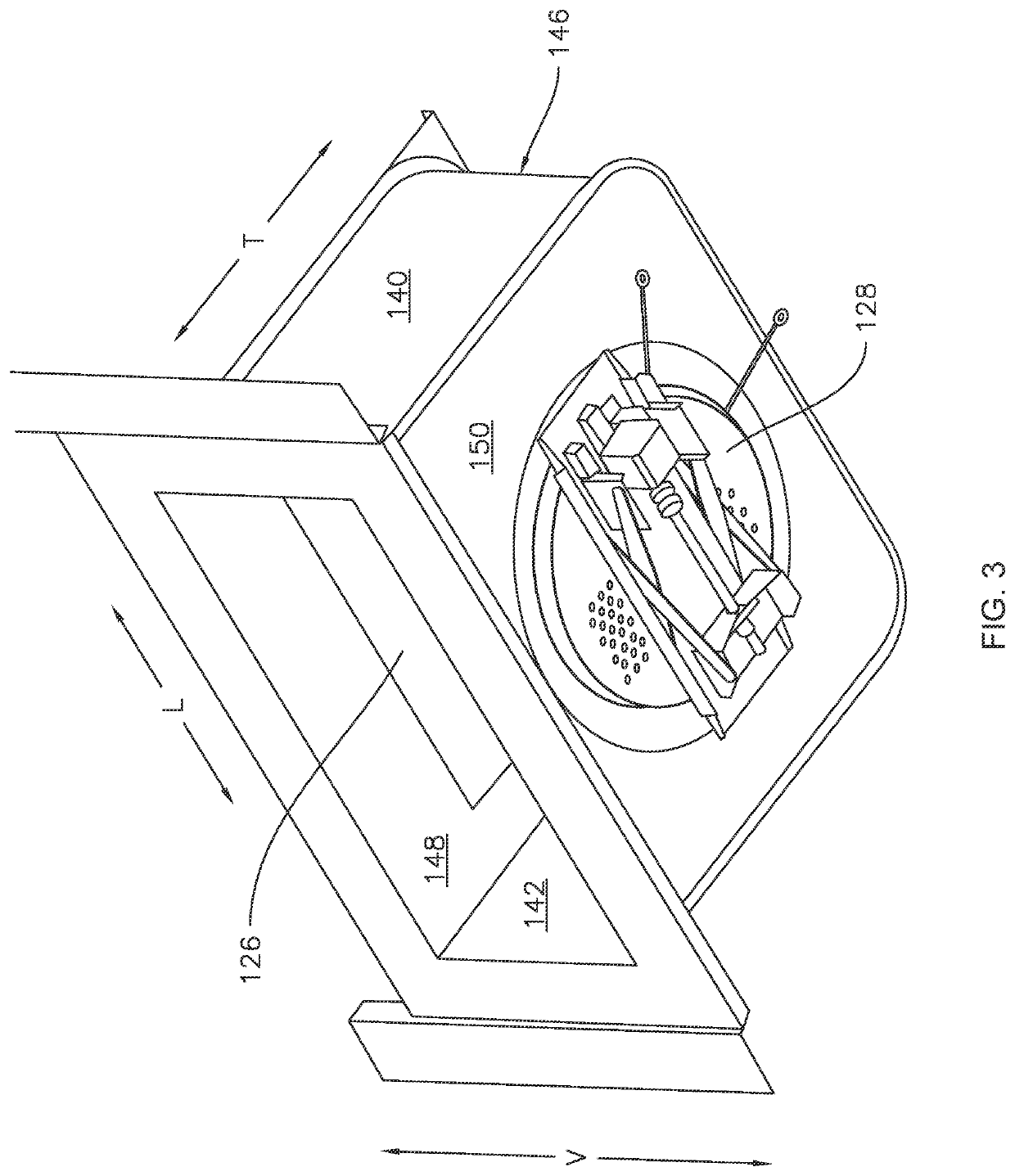
A cooking appliance includes a cabinet that defines a vertical direction and an inner shell positioned within the cabinet. The inner shell defines a cooking chamber therein. The cooking appliance also includes an upper heating module positioned at or proximate to an upper wall of the inner shell. The cooking appliance further includes a movable platform mounted to the inner shell within the cabinet. The movable platform is configured to move along the vertical direction between a bottom position wherein the movable platform is at least partially flush with a bottom wall of the inner shell and an elevated position wherein the movable platform is positioned above the bottom wall of the inner shell.

Description

FIELD OF THE INVENTION[0001]The present subject matter relates generally to cooking appliances, and more particularly to cooking appliances having features for moving food items therein closer to heating elements of the cooking appliance.BACKGROUND OF THE INVENTION[0002]Various cooking appliances include a cooking chamber defined inside of the appliance with multiple heat sources positioned in or proximate to the cooking chamber for providing heat to the cooking chamber and food items therein. The heat sources may include one or more of electrical resistance heating elements, heat lamps, a microwave energy source such as a magnetron, and / or an induction heating system. The multiple heat sources are typically spaced apart from each other within the cooking appliance. For example, one heat source may be an upper heat source positioned at or proximate to a top of the cooking chamber, and another heat source may be a lower heat source positioned at or proximate to a bottom of the cookin...

Claims


Application Information

Patent Timeline
IPC IPC(8): F24C15/16
CPCF24C15/16B66F7/065
Inventor LEE, BYUNG CHEON
Owner HAIER US APPLIANCE SOLUTIONS INC
Why Eureka
Try Eureka