Crimp terminal-equipped flexible printed circuit board and method for manufacturing same
a flexible printed circuit board and flexible technology, applied in the direction of printed circuit non-printed electric components, laminated printed circuit boards, fixed connections, etc., can solve the problems of easy deformation of mechanical difficulty in maintaining conduction and strength of each member, and increase in weight of fp
- Summary
- Abstract
- Description
- Claims
- Application Information
AI Technical Summary
Benefits of technology
Problems solved by technology
Method used
Image
Examples
first embodiment
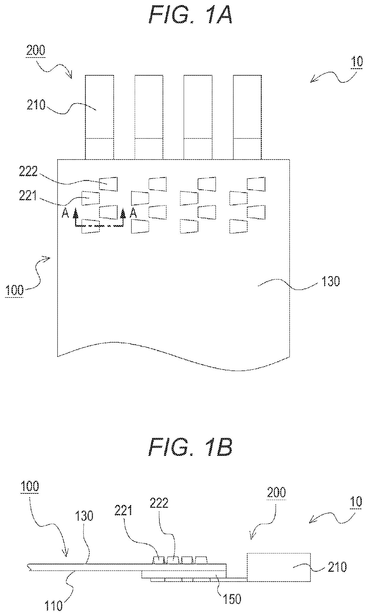
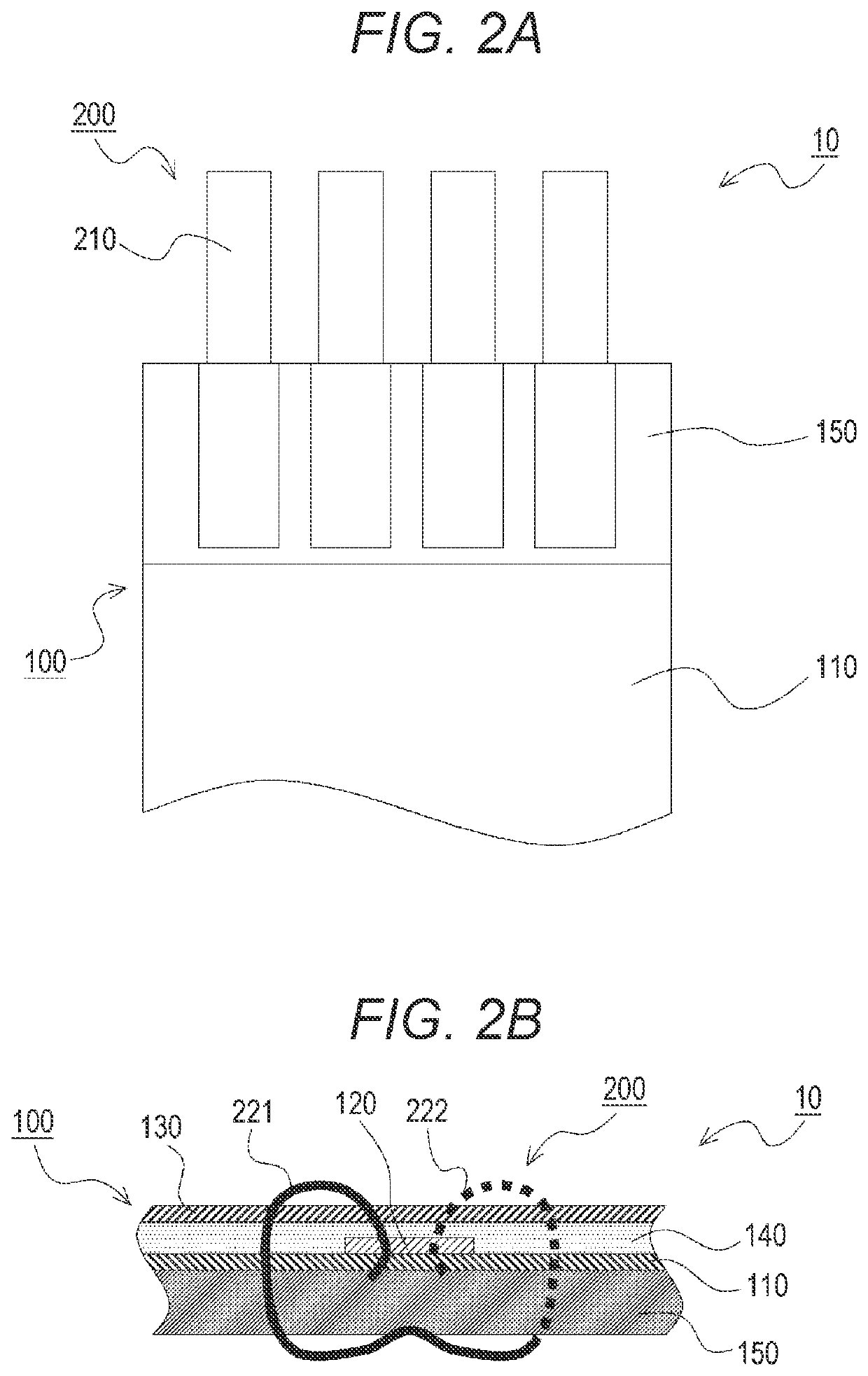
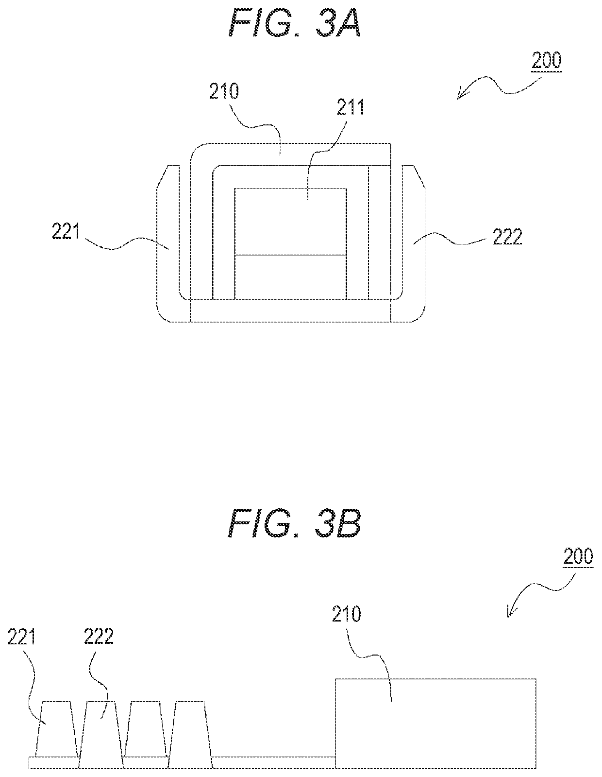
[0026]A crimp terminal-equipped flexible printed circuit board according to a first embodiment of the present disclosure will be described with reference to FIGS. 1A, 1B, 2A. 2B, 3A, and 3B. FIGS. 1A and 1B are schematic views of the configuration of the crimp terminal-equipped flexible primed circuit board according to the first embodiment of the present disclosure. FIG. 1A shows part of a plan view of the crimp terminal-equipped flexible printed circuit hoard. FIG. 1B shows part of a side view of the crimp terminal-equipped flexible printed circuit board. FIGS. 2A and 2B are schematic views of the configuration of the crimp terminal-equipped flexible printed circuit board according to the first embodiment of the present disclosure, FIG. 2A shows part of a back view of the crimp terminal-equipped flexible printed circuit board. FIG. 2B is a schematic sectional view of the crimp terminal-equipped flexible printed circuit board, and is a sectional view (not showing box portions of th...
second embodiment
[0035]FIGS. 4A, 4B, 5A, and 5B show a second embodiment of the present disclosure. In the configuration described in the first embodiment, the crimp terminals are attached to the FPC such that the crimp pieces pierce the FPC from the insulating reinforcing film side to the cover film side. On the other hand, in a configuration described in the present embodiment, crimp terminals are attached to an FPC such that crimp pieces pierce the FPC from a cover film side to an insulating reinforcing film side. The configuration of the FPC itself and the configuration of the crimp terminal itself are the same as those of the first embodiment, and therefore, the same reference numerals are used to represent the same components and description thereof will be omitted as necessary.
[0036]FIGS. 4A and 4B are schematic views of the configuration of the crimp terminal-equipped flexible printed circuit board according to the second embodiment of the present disclosure. FIG. 4A shows part of a back vie...
third embodiment
[0040]FIGS. 6A, 6B, 7A, and 7B show a third embodiment of the present disclosure. In the configurations described in the first and second embodiments, the cover film is entirely provided on the opposite side of the circuit from the base film in the FPC. On the other hand, in a configuration described in the present embodiment, no cover film is provided on the area of an FPC where crimp terminals are provided. Other basic configurations are the same as those of the first embodiment, and therefore, the same reference numerals are used to represent the same components and description thereof will be omitted as necessary.
[0041]FIGS. 6A and 6B are schematic views of the configuration of the crimp terminal-equipped flexible printed circuit board according to the third embodiment of the present disclosure. FIG. 6A shows part of a plan view of the crimp terminal-equipped flexible printed circuit hoard. FIG. 6B shows part of a side view of the crimp terminal-equipped flexible printed circuit...
PUM
 Abstract
Description
Claims
Application Information
 - R&D
- Intellectual Property
- Life Sciences
- Materials
- Tech Scout
- Unparalleled Data Quality
- Higher Quality Content
- 60% Fewer Hallucinations
Browse by: Latest US Patents, China's latest patents, Technical Efficacy Thesaurus, Application Domain, Technology Topic, Popular Technical Reports.
© 2025 PatSnap. All rights reserved.Legal|Privacy policy|Modern Slavery Act Transparency Statement|Sitemap|About US| Contact US: help@patsnap.com


