Electronically controlled depolarizer based on crossed-slit waveguide

a waveguide and electric control technology, applied in the field of integrated optical, can solve the problems of limiting the fiber-type lyot depolarizer, difficult to guarantee precise 45-degree fusion splice, and relatively fragile fusion spli

Pending Publication Date: 2022-09-29
ZHEJIANG UNIV
View PDF0 Cites 0 Cited by
  • Summary
  • Abstract
  • Description
  • Claims
  • Application Information

AI Technical Summary

Problems solved by technology

Moreover, it is difficult to guarantee precise 45-degree fusion splice.
The fusion splice...

Method used


Image

  • Electronically controlled depolarizer based on crossed-slit waveguide
  • Electronically controlled depolarizer based on crossed-slit waveguide

Examples


embodiment

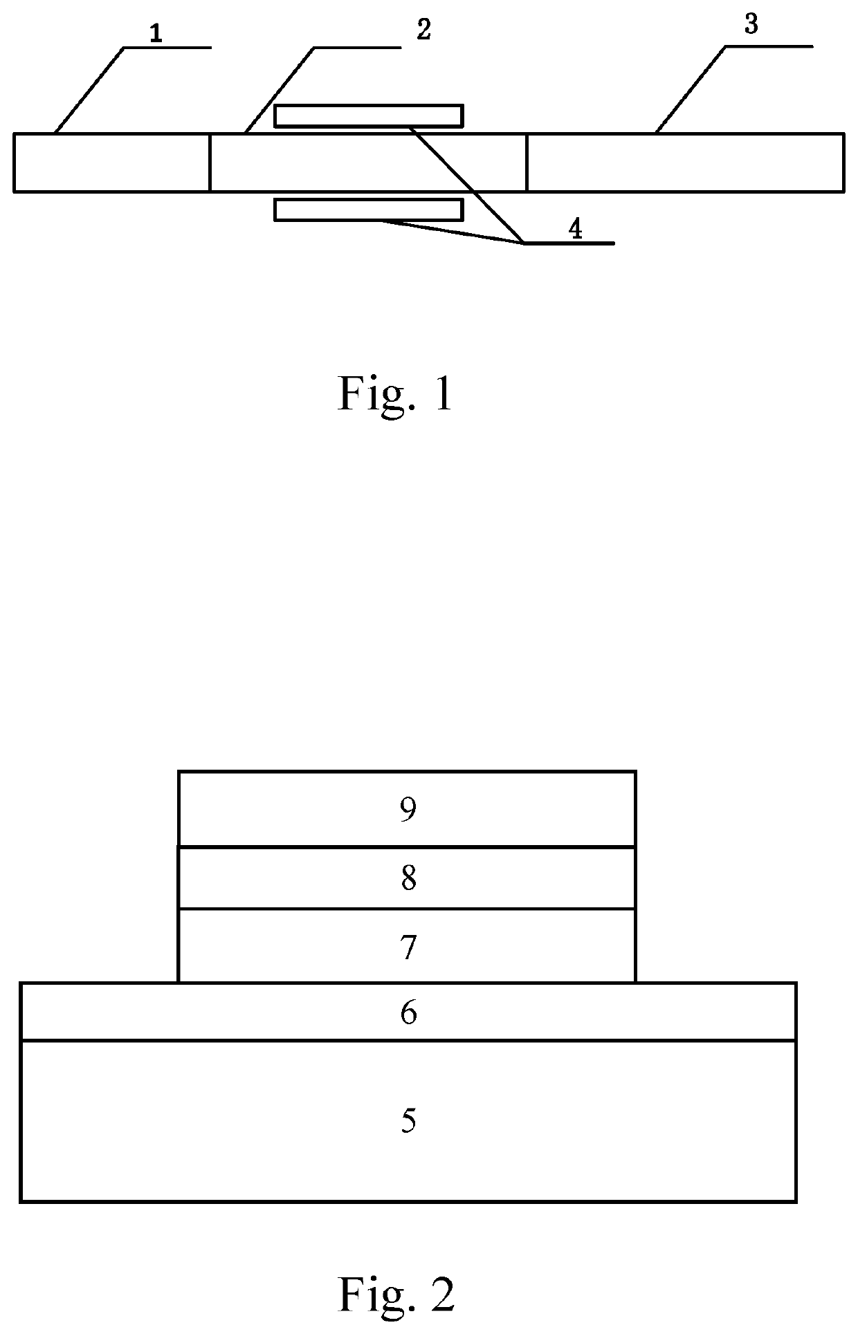
[0030]The broad-spectrum TM polarized light is inputted to the 45-degree polarization rotation waveguide 2 through the horizontal-slit waveguide 1, the 45-degree polarization rotation waveguide 2 converts a half of the broad-spectrum TM polarized light into the broad-spectrum TE polarized light; the broad-spectrum TE polarized light and the other half of the broad-spectrum TM polarized light, both of which are outputted from the 45-degree polarization rotation waveguide 2, enter an input end of the crossed-slit waveguide 3, the broad-spectrum TE polarized light is transmitted in the vertical slit of the crossed-slit waveguide 3, and the other half of the broad-spectrum TM polarized light is transmitted in the horizontal slit of the crossed-slit waveguide 3; the broad-spectrum TE polarized light and the other half of the broad-spectrum TM polarized light form depolarized light at an output end of the crossed-slit waveguide 3.

[0031]According to the preferred embodiment, the inputted b...


PUM


Abstract

An electrically controlled depolarizer based on a crossed-slit waveguide (3) includes a horizontal-slit waveguide (1), a 45-degree polarization rotation waveguide (2), a pair of modulation electrodes (4) and the crossed-slit waveguide (3). Broad-spectrum TM (transverse magnetic) polarized light is inputted from one end of the horizontal-slit waveguide (1), and then a part of the broad-spectrum TM polarized light is converted into broad-spectrum TE (transverse electric) polarized light through the 45-degree polarization rotation waveguide (2), and then the broad-spectrum TE polarized light and the remaining broad-spectrum TM polarized light enter an input end of the crossed-slit waveguide (3); the board-spectrum TE polarized light is transmitted in a vertical slit of the crossed-slit waveguide (3); the remaining broad-spectrum TM polarized light is transmitted in a horizontal slit of the crossed-slit waveguide (3); and the broad-spectrum TE polarized light and the remaining broad-spectrum TM polarized light form depolarized light at an output end of the crossed-slit waveguide (3). The pair of modulation electrodes (4) realize the precise adjustment of the rotation angle of the 45-degree polarization rotation waveguide (2) by electronic control, such that the TE polarized light and the TM polarized light at the output end of the crossed-slit waveguide (3) have equal energy, thereby overcoming uneven light splitting caused by loss of the polarization rotation waveguide and TE and TM waveguide transmission loss.

Description

BACKGROUND OF THE PRESENT INVENTIONField of Invention[0001]The present invention relates to the integrated optical field, and more particularly to an electronically controlled depolarizer based on a crossed-slit waveguide.Description of Related Arts[0002]The depolarizer is a passive polarization device which is able to convert polarized light into unpolarized light. It is used in fiber-optic gyroscopes, fiber sensors, high-precision spectrophotometers, photoelectric detectors, and Raman amplifiers. According to the implementation method, the depolarizer is able to be divided into electro-optical type depolarizer, sound-controlled type depolarizer and Lyot type depolarizer, wherein the Lyot type depolarizer is suitable for wide-spectrum light sources, is simple and practical, and is a widely used depolarizer. The Lyot type fiber depolarizer includes two high-birefringence polarization maintaining fibers with a length ratio of 1:2 and a birefringent main axis angle of 45°. Its working...

Claims


Application Information

Patent Timeline
IPC IPC(8): G02B6/126G02F1/035
CPCG02B6/126G02F1/035G02B6/125G02B2006/1204G02B6/2786G02B6/2726
Inventor SHE, XUANYAO, JUNJIECHEN, KANHUANG, TENGCHAOSHU, XIAOWU
Owner ZHEJIANG UNIV
Why Eureka
Try Eureka