
Nonlinear optical raman devices with zig-zag beam paths

a beam path and optical raman technology, applied in nonlinear optics, instruments, optics, etc., can solve the problems of not being practical for collinear phase matching schemes, the use of huang design is limited to relatively thin solid-state nonlinear media,

Active Publication Date: 2022-09-29
JGM ASSOC
View PDF6 Cites 1 Cited by
  • Summary
  • Abstract
  • Description
  • Claims
  • Application Information

AI Technical Summary

Benefits of technology

This design effectively mitigates back-conversion, improves beam quality, and allows for flexible phase-matching schemes, enhancing the efficiency and performance of nonlinear optical devices such as optical parametric oscillators and amplifiers by controlling the intensity of non-resonated waves and optimizing the zig-zag path and resonator design.

Problems solved by technology

Accordingly, the Komine method is practically limited to use with relatively thin solid-state nonlinear media (thickness of 500 microns or less).
However, in the Huang method, the pump beam necessarily makes a straight-through pass in the nonlinear medium and does not follow a zig-zag beam path.
The Huang design may not be practical for use with collinear phase-matching schemes.

Method used


Image

  • Nonlinear optical raman devices with zig-zag beam paths
  • Nonlinear optical raman devices with zig-zag beam paths
  • Nonlinear optical raman devices with zig-zag beam paths

Examples


Embodiment Construction

[0069]The following detailed description is of the best currently contemplated modes of carrying out the invention. The description is not to be taken in a limiting sense, but is made merely for the purpose of illustrating the general principles of the invention. The detailed descriptions of embodiments provided below are intended only to be exemplary and explanatory and are not intended to be restrictive of, or on, the invention.

[0070]Unless indicated otherwise, “highly reflecting” indicates a high reflectivity value in the range of 95% R to 100% R at the wavelength in question, “partially reflecting (PR)” indicates a reflectivity in the range of 10% R to 95% R, “highly transmitting (HT)” indicates a transmission value in the range of 90% T to 100% T, and “partially transmitting (PT)” indicates a transmission in the range of 10% T to 90% T. However, in general, the terms HR, HT, PR, and PT are understood by someone well-versed in the art and the above definitions are not intended t...


PUM

PropertyMeasurementUnit
anglesaaaaaaaaaa
wedge angle Baaaaaaaaaa
angleaaaaaaaaaa

Abstract

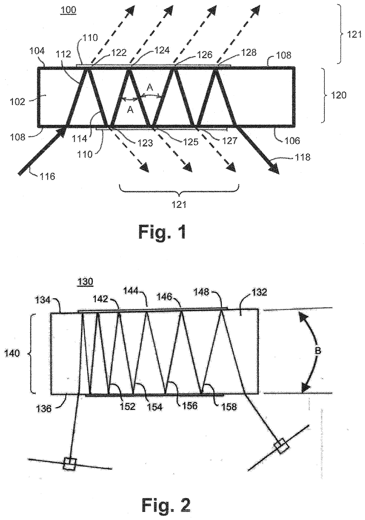
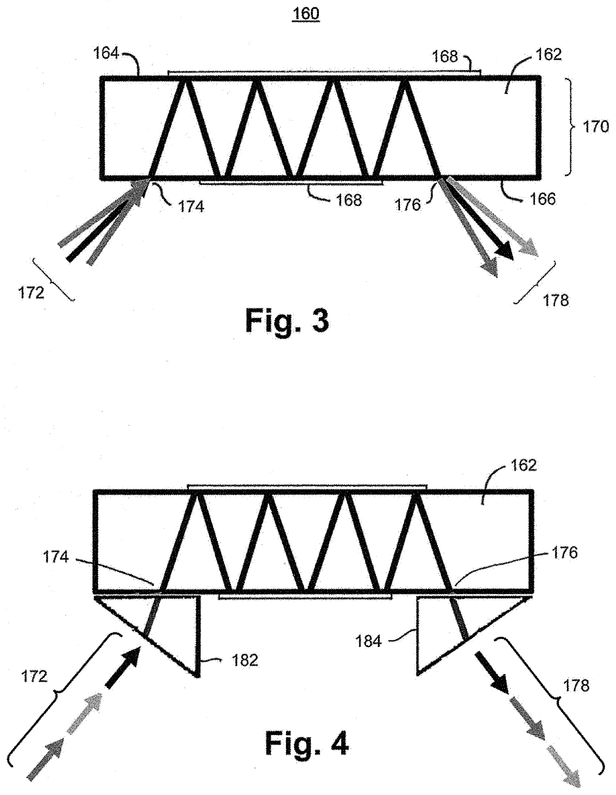
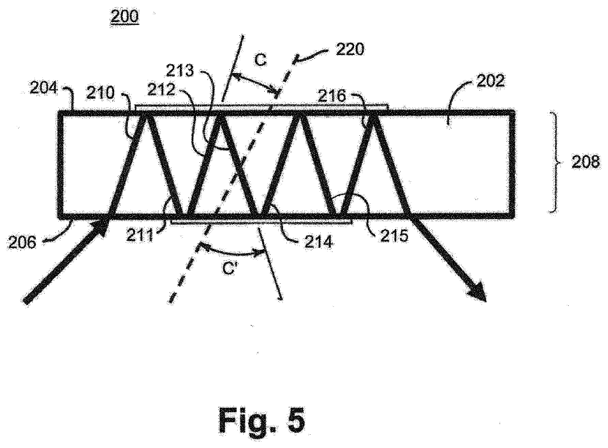
The invention is a nonlinear Raman optical device generating zig-zag radiation beam paths in a nonlinear medium having dichroic coatings reflecting at a pump radiation wavelength, with a first mirror between an injected beam of pump radiation and a first end of the nonlinear medium and a second mirror at a second end of the nonlinear medium, the second mirror being partially reflecting at a first Stokes wavelength of the pump radiation.

Description

CROSS REFERENCE TO RELATED APPLICATION[0001]The present application is a division of U.S. Pat. No. 11,360,369 entitled “Nonlinear Optical Devices with Zig-zag Beam Paths.”FIELD OF THE INVENTION[0002]The invention relates to sources of coherent laser emission that use nonlinear optical methods to convert coherent light emission at one or more input wavelengths to coherent light emission at one or more output wavelengths. The invention employs a zig-zag beam propagation path, configured using dichroic thin-film or other dichroic optical coatings on one or more optical surfaces to control to some aspect of the wavelength conversion process. Such aspects might include emitted beam quality, the combination of wavelengths being generated, and conversion efficiency into a specific wavelength, among others.BACKGROUND OF THE INVENTION[0003]Nonlinear optical methods or processes are widely used for converting the wavelength(s) of coherent electromagnetic light emission from an input source, o...

Claims


Application Information

Patent Timeline
Patent Type & Authority Applications(United States)
IPC IPC(8): G02F1/39G02F1/35
CPCG02F1/39G02F1/3501G02F1/392G02F1/3503
Inventor MANNI, JEFFREY G.
Owner JGM ASSOC
Learn More