Hld module with improved cooling of a luminescent body

a luminescent body and module technology, applied in the field of light generating systems, can solve the problems of limiting affecting the efficiency of such illumination systems, and affecting the efficiency of such illumination systems

Pending Publication Date: 2022-10-27
SIGNIFY HLDG BV
View PDF0 Cites 0 Cited by
  • Summary
  • Abstract
  • Description
  • Claims
  • Application Information

AI Technical Summary

Problems solved by technology

These second light rays are lost and may limit the efficiency of such illumination systems.
Typically, 44% of the converted lig

Method used


Image

  • Hld module with improved cooling of a luminescent body
  • Hld module with improved cooling of a luminescent body
  • Hld module with improved cooling of a luminescent body

Examples


Embodiment Construction

[0195]A light emitting device according to the invention may be used in applications including but not being limited to a lamp, a light module, a luminaire, a spot light, a flash light, a projector, a (digital) projection device, automotive lighting such as e.g. a headlight or a taillight of a motor vehicle, arena lighting, theater lighting and architectural lighting.

[0196]Light sources which are part of the embodiments according to the invention as set forth below, may be adapted for, in operation, emitting light with a first spectral distribution. This light is subsequently coupled into a light guide or waveguide; here the light transmissive body. The light guide or waveguide may convert the light of the first spectral distribution to another spectral distribution and guides the light to an exit surface.

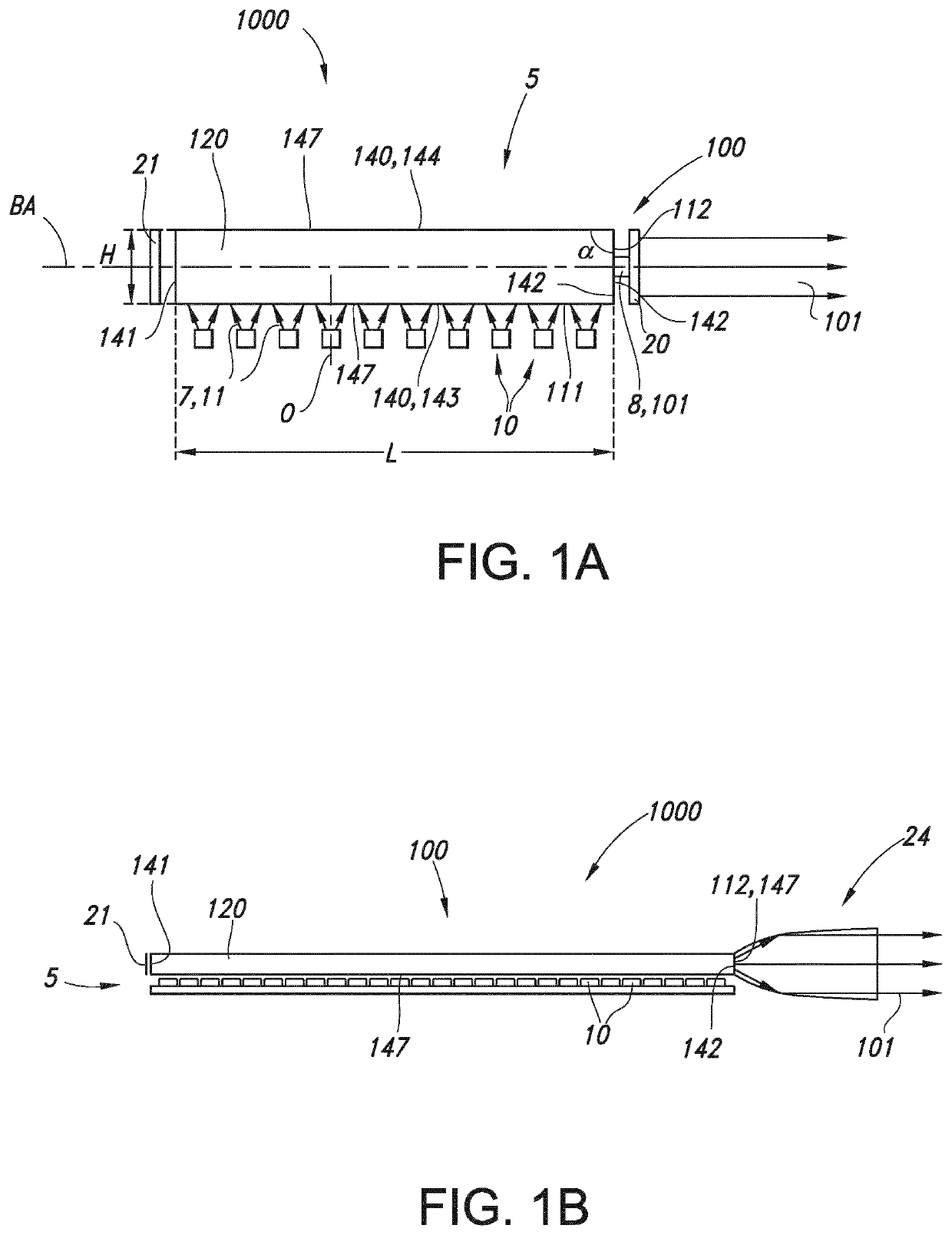
[0197]An embodiment of the light generating system as defined herein is schematically depicted in FIG. 1a. FIG. 1a schematically depicts a light generating system 1000 comprising a...


PUM


Abstract

The invention provides a light generating system (1000) comprising: —a plurality of k light sources (10) configured to provide light source light (11), wherein k is a natural number of at least 5, wherein the light sources (10) are configured in an array (15), wherein the light sources (10) have inter-light source distances (d1); —an elongated luminescent body (100) having a length (L), the elongated luminescent body comprising one or more side faces (140), the elongated luminescent body (100) comprising a radiation input face (111) and a radiation exit window (112), wherein the radiation input face (111) is configured in a light receiving relationship with the plurality of light sources (10), wherein the elongated luminescent body (100) comprises luminescent material (120) configured to convert at least part of light source light (11) into luminescent material light (8), wherein the radiation exit window (112) has an angle (α) unequal to 0° and unequal to 180° with the radiation input face (111); —a body holder structure (2000), wherein the body holder structure (2000) comprises an elongated slit (205) for hosting the elongated luminescent body (100), wherein the elongated slit (205) comprises one or more slit side faces (2140); —n force applying elements (1300) configured to keep the elongated body (100) pushed against at least one of the one or more slit side faces (2140) of the elongated slit (205), wherein n is a natural number selected from the range of 0.01*L/mm-0.05*L/mm, wherein the length (L) is in mm, wherein n is at least 1, and wherein the inter-light source distance (d1) at the n force applying elements (1300) is larger than an average inter-light source distance (d1).

Description

FIELD OF THE INVENTION[0001]The invention relates to a light generating system, such as for use in a projector or for use in stage lighting, or for use for microscopy or endoscopy illumination. The invention also relates to a luminaire or projection system comprising such light generating system.BACKGROUND OF THE INVENTION[0002]Luminescent rods are known in the art. WO2006 / 054203, for instance, describes a light emitting device comprising at least one LED which emits light in the wavelength range of >220 nm to <550 nm and at least one conversion structure placed towards the at least one LED without optical contact, which converts at least partly the light from the at least one LED to light in the wavelength range of >300 nm to ≤1000 nm, characterized in that the at least one conversion structure has a refractive index n of >1.5 and <3 and the ratio A:E is >2:1 and <50000:1, where A and E are defined as follows: the at least one conversion structure comprises at ...

Claims


Application Information

Patent Timeline
IPC IPC(8): F21V8/00
CPCG02B6/0003G02B6/0068G02B6/0085G02B6/0055
Inventor YU, JIANG HONGBRULS, DOMINIQUE MARIA
Owner SIGNIFY HLDG BV
Why Eureka
Try Eureka