
Camera Platform and Track

a technology of platform and track, applied in the direction of machine supports, instruments, etc., can solve the problems of distorting or moving the track, affecting the efficiency of the platform, and creating undesirable environmental nois

Pending Publication Date: 2022-10-27
PETERSON PER
View PDF0 Cites 0 Cited by
  • Summary
  • Abstract
  • Description
  • Claims
  • Application Information

AI Technical Summary

Benefits of technology

The present invention is a camera platform track that offers increased strength and torsional rigidity compared to existing tracks. The track includes top and lower running surfaces for multiple camera platforms, preventing them from wandering during filming. The track also includes grooves to improve traction and lateral spacing to reduce or eliminate wandering. Additionally, a box supporting an I-beam is included to provide a light weight track while still maintaining torsional rigidity. Overall, this invention provides a more stable and versatile track for filming.

Problems solved by technology

Known camera platform tracks only support a single camera platform, or two or more camera platforms on the same running surfaces, not allowing independent movement for filming.
Unfortunately, cameras having a wide-angle (or short focal length) lens preferably move faster on a platform than cameras having a long focal length, and independent motion of cameras is required to edit with a non contrasting tempo of the cameras.
Known tracks have smooth running surfaces which do not facilitate efficient operation of friction drive motors for isolated / remote operation and slipping distorts filming and creates undesirable environmental noise.
Motor driven camera platforms press against the I-beam structure and often distort or move the track.
A sufficiently strong I-beam track is generally too heavy for easy movement and assembly, and requires a height likely to cause tripping and injury.
The '782 patent thus fails to address torsional liabilities and flexing issues which were only discovered by later use of the track.
The track of the '421 patent does not allow two or more independent cameras.

Method used


Image

  • Camera Platform and Track
  • Camera Platform and Track
  • Camera Platform and Track

Examples


Embodiment Construction

[0032]The following description is of the best mode presently contemplated for carrying out the invention. This description is not to be taken in a limiting sense, but is made merely for the purpose of describing one or more preferred embodiments of the invention. The scope of the invention should be determined with reference to the claims.

[0033]Where the terms “about” or “generally” are associated with an element of the invention, it is intended to describe a feature's appearance to the human eye or human perception, and not a precise measurement, or typically within 10 percent of a stated value.

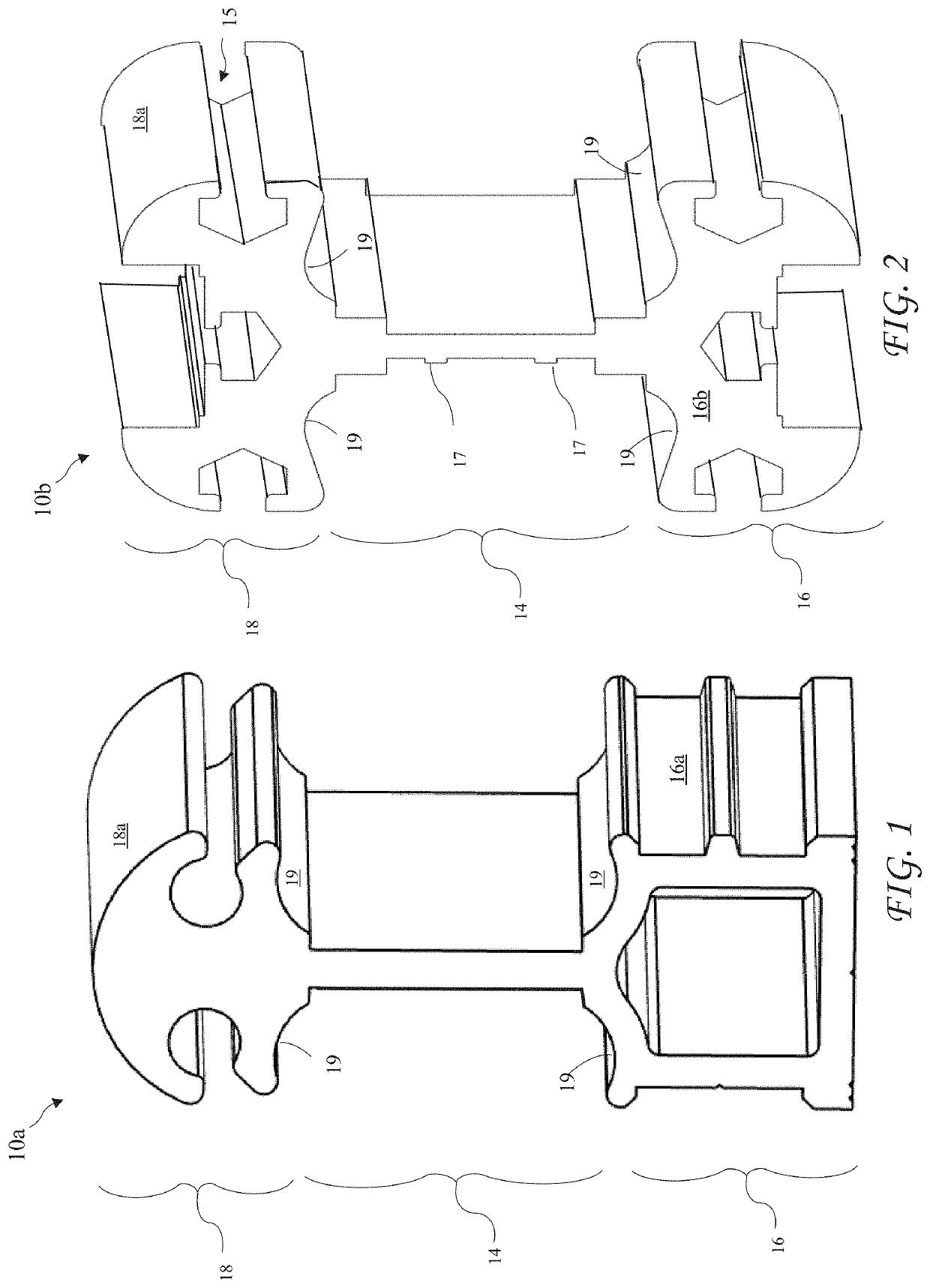
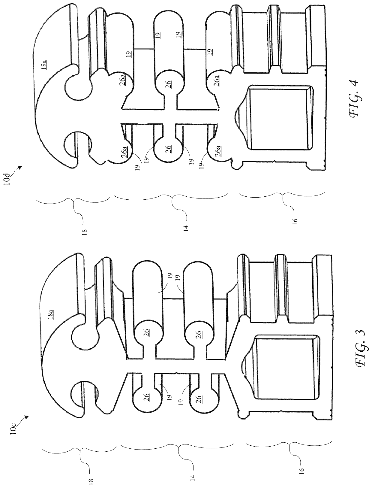
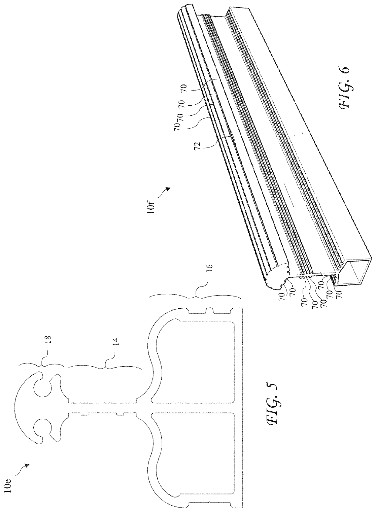
[0034]A first camera platform track 10a according to the present invention is shown in FIG. 1. The track 10a includes torsion structure 16a (for example a box portion), a vertical I-beam portion 14 above the torsion structure 16a, and a top portion 18 above the I-beam portion 14. A top running surface 18a is formed on the top portion 18 and lower running surfaces 19 are formed on the bottom...


PUM


Abstract

A camera platform track provides running surfaces for independent movement of two or more camera platforms, improves strength to weight ratio, improves torsional rigidity, restricts camera platforms from wandering during filming, and improves traction. The camera platform track includes top running surfaces for a first camera platform, and one or more lower running surfaces for additional camera platforms, allowing desired versatility in filming. The camera platform tracks include a box base and an I-beam reaching up from the base to provide strength and torsional rigidity without excessive weight. The running surface lateral spacing may vary from camera platform wheel spacing providing centering to reduce or eliminate wandering, and may include grooves to improve traction. wandering, and may include grooves to improve traction.

Description

CROSS-REFERENCE TO RELATED APPLICATIONS[0001]The present application claims the priority of U.S. Provisional Patent Application Ser. No. 63 / 178,122 filed Apr. 22, 2021, which application is incorporated in its entirety herein by reference.BACKGROUND OF THE INVENTION[0002]The present invention relates camera platform tracks and in particular to camera platform tracks used in the motion picture industry.[0003]Known camera platform tracks only support a single camera platform, or two or more camera platforms on the same running surfaces, not allowing independent movement for filming. The cameras may be operated manually propelled by human power, or remotely by motorized devices. Unfortunately, cameras having a wide-angle (or short focal length) lens preferably move faster on a platform than cameras having a long focal length, and independent motion of cameras is required to edit with a non contrasting tempo of the cameras. Shooting single explosions or action sequences, for dramatic ef...

Claims


Application Information

Patent Timeline
IPC IPC(8): G03B17/56E01B23/02
CPCG03B17/561E01B23/02F16M11/425F16M11/18
Inventor PETERSON, PER
Owner PETERSON PER
Learn More