
Friction transmission belt

a transmission belt and friction technology, applied in the direction of layered products, mechanical equipment, chemistry equipment and processes, etc., can solve the problems of abnormal sound generation and slip sound, and achieve the effect of reducing the abnormal sound generated during water exposur

Pending Publication Date: 2022-11-03
BANDO CHEM IND LTD
View PDF0 Cites 0 Cited by
  • Summary
  • Abstract
  • Description
  • Claims
  • Application Information

AI Technical Summary

Benefits of technology

The present invention is a friction transmission belt that has a reduced decrease in friction coefficient during water exposure. This helps to prevent the belt from generating excessive noise during water exposure and also reduces the likelihood of stick-slip.

Problems solved by technology

It is known that a friction transmission belt (hereinafter, referred to as transmission belt) causes a phenomenon called stick-slip when being exposed to water during operation, and this phenomenon may be accompanied by generation of abnormal sound, in other words, slip sound.

Method used

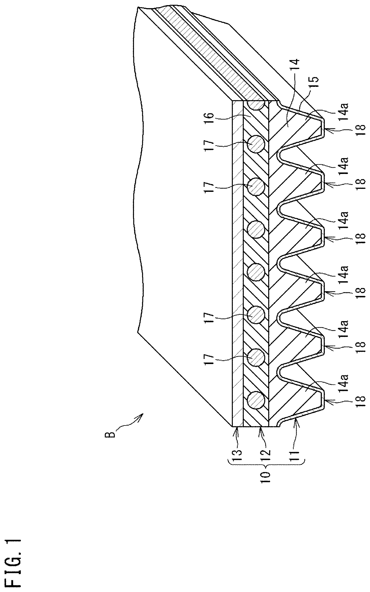

Image

  • Friction transmission belt
  • Friction transmission belt
  • Friction transmission belt

Examples


example 1

[0139]A V-ribbed belt that has the same configuration as described above in the embodiment and in which the knitted fabric A was used as a fiber member layer and the above-described ones were used as a compression rubber layer body material, an adhesive rubber layer body material, a core wire, and a backface reinforcing fabric, was produced by the manufacturing method described with reference to FIG. 5A to FIG. 6C, and was regarded as a V-ribbed belt of Example 1.

[0140]In Example 1, the stretching ratio of the fiber member layer was set to 180%, and the molding pressure was set to 0.7 MPa. The void ratio of the surface layer portion of the compression rubber layer was 38%.

example 5

[0143]A V-ribbed belt of Example 5 was produced in the same manner as Example 1, except that the knitted fabric B was used for the fiber member layer and the stretching ratio and the molding pressure were set as shown in Table 2 below.

[0144]In Example 5, the void ratio of the surface layer portion was 22%.

example 6

[0145]A V-ribbed belt of Example 6 was produced in the same manner as Example 1, except that the knitted fabric C was used for the fiber member layer and the stretching ratio and the molding pressure were set as shown in Table 2 below.

[0146]In Example 6, the void ratio of the surface layer portion was 20%.

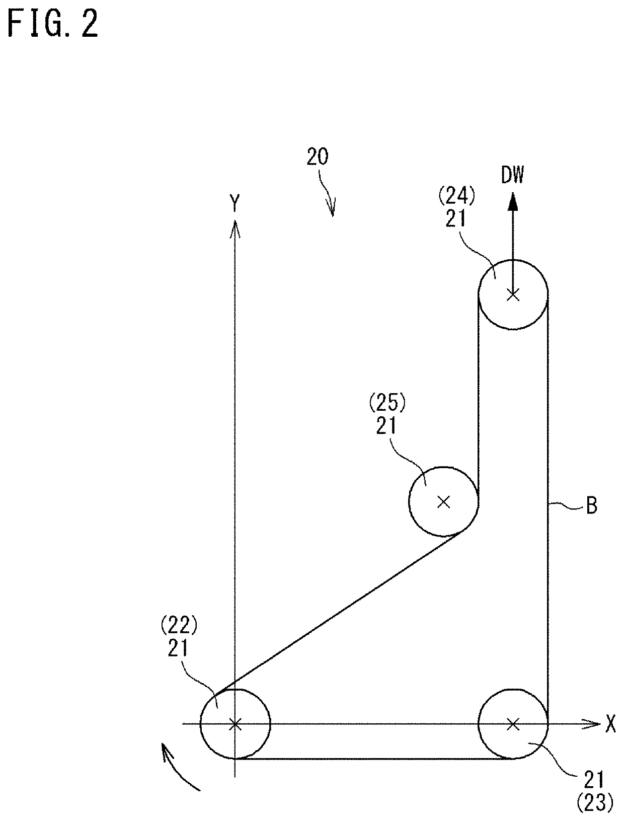
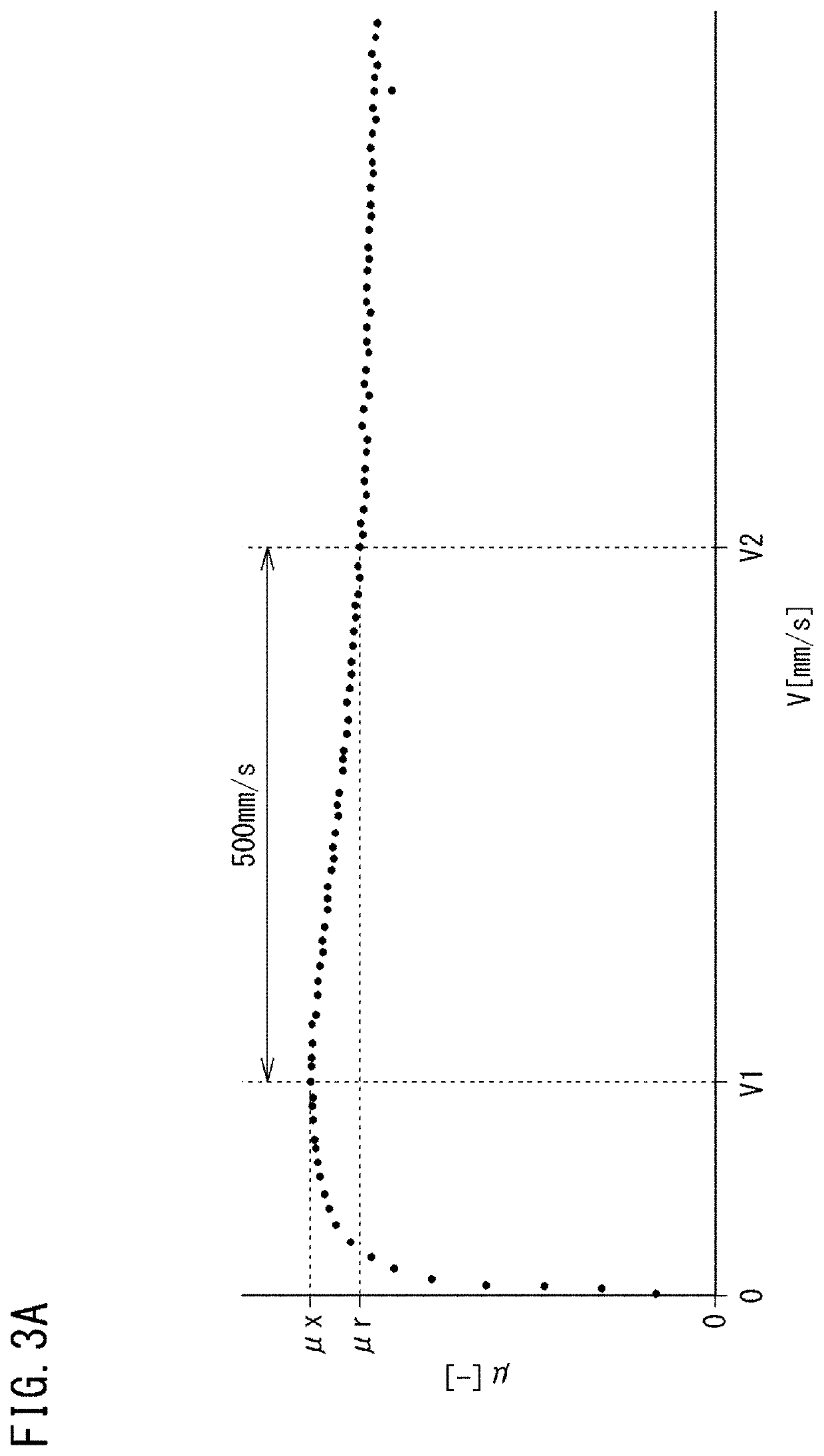
[0147]Using the belt running tester 20 shown in FIG. 2, the relationship between a slipping speed and a friction coefficient was obtained for Examples 1 to 6 and Comparative Example 1 according to the above-described evaluation method, and the decrease rate Dm of the friction coefficient indicated by the above-described equation (1) was obtained. Furthermore, the zone from the first slipping speed V1 to the second slipping speed V2 was equally divided into five sections, and the decrease rate Dsm of the friction coefficient indicated by the above-described equation (2), that is, the decrease rates Ds1, Ds2, Ds3, Ds4, and Ds5, were obtained for the respective sections. The results a...


PUM


Abstract

A friction transmission belt includes a belt body which transmits power to a pulley. In a relationship between a friction coefficient and a slipping speed which is a difference between a speed of the belt body and a speed of the pulley, when a slipping speed at which a maximum friction coefficient is indicated is defined as a first slipping speed, a friction coefficient when the slipping speed is increased from the first slipping speed to a second slipping speed is defined as a reference friction coefficient, and a difference between the second slipping speed and the first slipping speed is 500 mm / s, a decrease rate Dm of the friction coefficient indicated by the following equation (1) with the maximum friction coefficient being denoted by μx and the reference friction coefficient being denoted by μr is not greater than 20%.Dm=(μx−μr) / μx×100  (1)

Description

TECHNICAL FIELD[0001]The present invention relates to a friction transmission belt.[0002]This application claims priority on Japanese Patent Application No. 2021-077767 filed on Apr. 30, 2021, the entire content of which is incorporated herein by reference.BACKGROUND ART[0003]Conventionally, as a means for transmitting rotational power of an engine, a motor, or the like, a method in which pulleys are fixedly provided on rotation shafts on a driving side and a driven side, respectively, and a friction transmission belt such as a V-ribbed belt is trained around each pulley, has been widely used.[0004]It is known that a friction transmission belt (hereinafter, referred to as transmission belt) causes a phenomenon called stick-slip when being exposed to water during operation, and this phenomenon may be accompanied by generation of abnormal sound, in other words, slip sound. The slip sound of the transmission belt causes noise of a device, so that various countermeasures have been consi...

Claims


Application Information

Patent Timeline
IPC IPC(8): F16G5/08F16G5/20
CPCF16G5/08F16G5/20F16G1/28F16G1/10F16G1/06F16G5/04B32B25/10
Inventor SHINDO, YUYAKOBAYASHI, SHOGO
Owner BANDO CHEM IND LTD
Learn More