A device and method for greatly increasing pullout resistance in soil layer anchorage
A technology of pullout resistance and anchorage, which is applied in construction, foundation structure engineering, sheet pile walls, etc., can solve the problems of sliding between the anchor rod and the anchor body, so as to improve the pullout resistance and support effect of the anchor rod, and reduce the contact Probability of water and air, effect of improving pullout resistance
- Summary
- Abstract
- Description
- Claims
- Application Information
AI Technical Summary
Problems solved by technology
Method used
Image
Examples
Embodiment 1
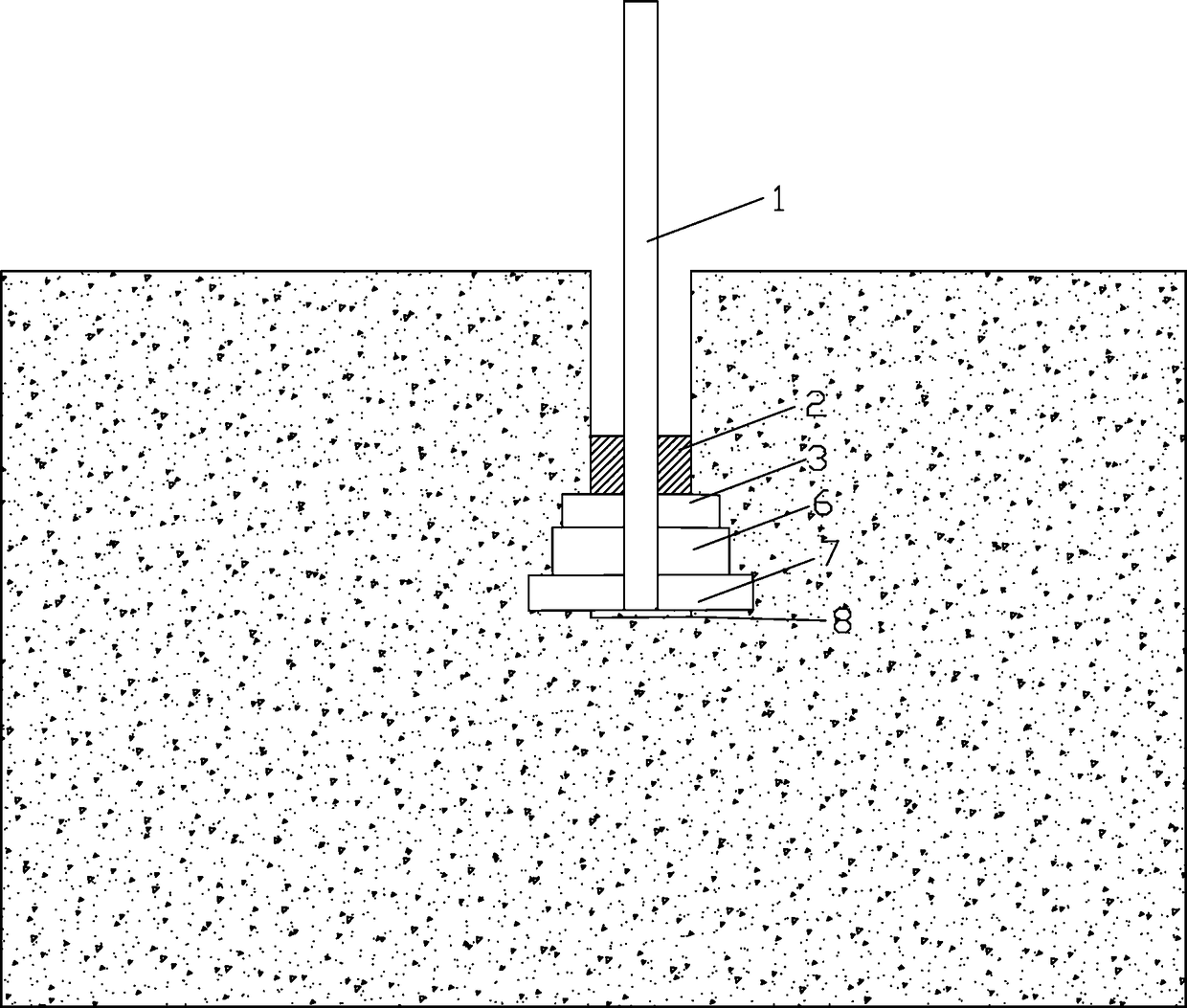
[0058] Such as figure 1 Shown, a kind of device that greatly improves pullout resistance in the anchorage of soil layer comprises the anchor rod 1 that has rigid disk 8 (preferably iron disk) at the bottom that is placed in anchor hole 5, and rigid disk 8 is placed on At the bottom of the anchor hole 5, the inner space of the anchor hole 5 on the rigid disc 8 is respectively poured with
[0059] The first expansive cement layer 7, the second expansive cement layer 6, the third expansive cement layer 3,
[0060] The amount of expansion agent X in the expansive cement slurry used in the first expansive cement layer 7 1 = 20%;
[0061] The expansion agent dosage X in the expansive cement slurry used in the second expansive cement layer 6 2 = 15%;
[0062] The expansion agent dosage X in the expansive cement slurry used in the third expansive cement layer 3 3 = 10%;
[0063] The amount of expansion agent Xn = expansion agent quality / (expansion agent quality + cement qualit...
Embodiment 2
[0068] A method for greatly improving the pull-out resistance by using the device described in Embodiment 1 to form a multi-layer expansion head, the method includes the following steps:
[0069] Step 1: Select a stable supporting slope, remove the debris on the surface and dig out the soft soil layer on the surface;
[0070] Step 2: drilling: drilling on the support slope to form the anchor hole 5, the height of the anchor hole is 1.5 meters, and the diameter is 6 cm;
[0071] Step 3: Make the anchor rod 1 with the rigid disk 8 at the bottom, the length of the anchor rod 1 is 1.8 meters, and the outer diameter is 22 mm;
[0072] Step 4: Prepare expansive cement slurry with different expansion agent content Xn, n=1, 2, 3...N, X 1 = 20%, X 2 = 15%, X 3 = 10%;
[0073] The preparation method is as follows:
[0074] Prepare expansive cement slurry with expansion agent content of 10%, 15%, and 20% and cement slurry without expansion agent, that is, take ordinary portland ceme...
Embodiment 3
[0079] The device installed in embodiment two is carried out pressure test and pull-out force pull-out test,
[0080] Paste the strain gages on the anchor rod 1 before putting the anchor rod 1 into the anchor hole: paste the strain gauges at equal intervals (10 cm) according to the length of the anchor section l, weld the lead wires of the strain gauges to the wires with tin soldering, and apply 704 sealing glue , and wrap it with insulating tape, and finally measure the resistance of the strain gauge (generally 120 ohms) to check the sticking effect of the strain gauge, and fix the strain gauge and the connecting wire on the anchor rod body with insulating tape so that it can be connected with the anchor rod 1 together. Put it in the anchor hole 5.
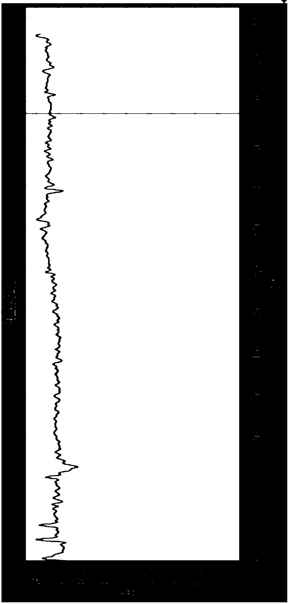
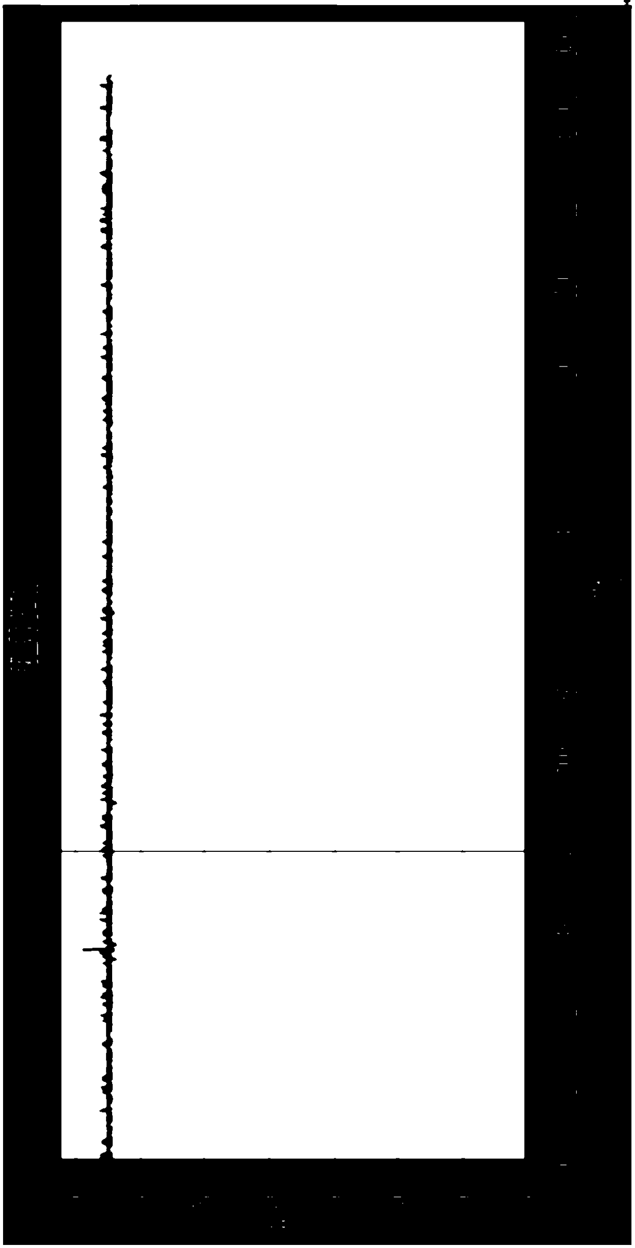
[0081] After all the grouting is completed, use the pressure acquisition system to carry out a pressure test on the installed device, that is, to test the change of the expansion pressure from the initial setting of the expansion...
PUM
| Property | Measurement | Unit |
|---|---|---|
| height | aaaaa | aaaaa |
| length | aaaaa | aaaaa |
Abstract
Description
Claims
Application Information
 - R&D
- Intellectual Property
- Life Sciences
- Materials
- Tech Scout
- Unparalleled Data Quality
- Higher Quality Content
- 60% Fewer Hallucinations
Browse by: Latest US Patents, China's latest patents, Technical Efficacy Thesaurus, Application Domain, Technology Topic, Popular Technical Reports.
© 2025 PatSnap. All rights reserved.Legal|Privacy policy|Modern Slavery Act Transparency Statement|Sitemap|About US| Contact US: help@patsnap.com


