Continuous dispensing system for liquids

a liquid dispensing system and liquid technology, applied in liquid handling, liquid transfer devices, instruments, etc., can solve the problems of complex known devices, difficult to maintain exact dosing, and inaccurate metering systems of commercially available metering systems at flow rates below 5 liters

Inactive Publication Date: 2000-01-04
E M E NV +1
View PDF23 Cites 43 Cited by
  • Summary
  • Abstract
  • Description
  • Claims
  • Application Information

AI Technical Summary

Problems solved by technology

Further, in systems in which many liquids: are mixed together before processing, the mixed materials and partly processed materials often cannot be reused so that they must be disposed of and become waste.
However, mixing small quantities together means that it is more difficult to maintain exact dosing as the absolute tolerances reduce in proportion to the amount mixed.
In general, commercially available metering systems become inaccurate at flow rates below 5 liters per hour.
This known device is complex and requires very careful adjustment and maintenance.
It is designed for laboratory instruments and is unsuitable for industrial processes.
One disadvantage of this system is that a knowledge of how much material has been dispensed can only be calculated discontinuously at the end of each emptying cycle.
Such a system may be subject to hunting, i.e. that the feed back control system over compensates and under-compensates alternatingly so that the system never reaches stability and never gives a continuous flow.
Further, the system cannot react to changes in flow during one cycle.
However, this has the disadvantage that the range of flow rates which can be dispensed accurately is reduced or that the same accuracy cannot be obtained over the whole range.
This known device does not control the flow continuously and suffers from having no feedback control.
This known device has the disadvantage that the flow is discontinuous.
This reduce., the range of flow rates which can be dispensed effectively.
Further, as gravity feed is used, the range of viscosities of the solution and the output pressure of the known device is restricted.
Still another problem may be caused by non-linearities in the system.
This known system has serious disadvantages when a plurality of liquids are to be dispensed.
The number of points which have to be stored in the computer can be so great that the computer system becomes expensive and slow.
This means that the system takes a long time to set up and is riot very flexible.
This known method has the disadvantage that after a machine malfunction, the large quantity of mixed paint in the mixing vessel may have to be discarded.
Further, there are errors in colors which cannot be compensated for by the proposed technique without discarding some paint. e.g. if one of the color components is in a considerable excess it may be impossible to compensate for the error by the addition of other colors.

Method used


Image

  • Continuous dispensing system for liquids
  • Continuous dispensing system for liquids
  • Continuous dispensing system for liquids

Examples


Embodiment Construction

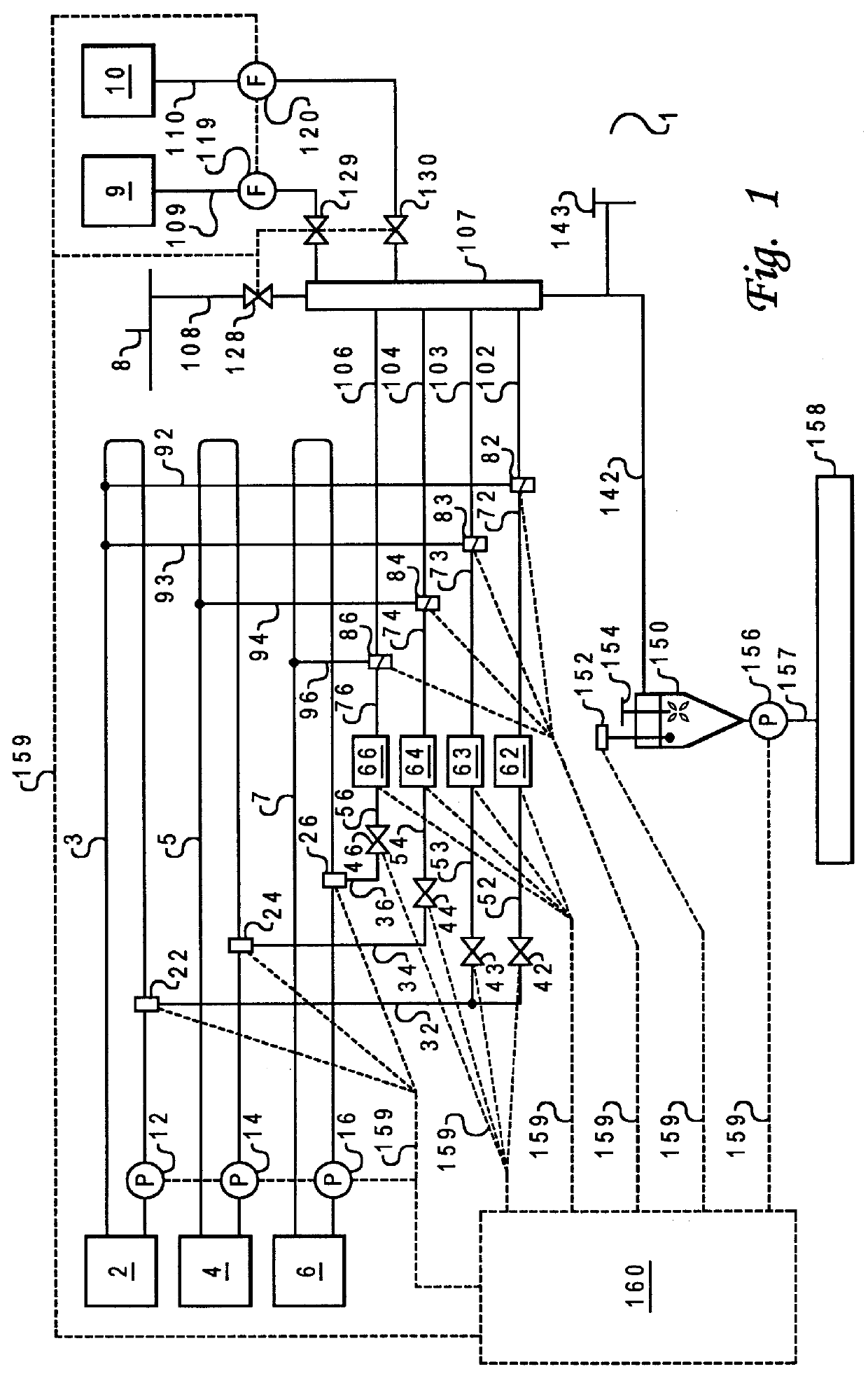
In the following the present invention will be described with reference to specific embodiments and with reference to the drawings but the invention is not limited thereto but only by the claims. The drawings are only schematic representations and are non-limiting. In particular, certain dimensions may be exaggerated for clarity purposes. The present invention will be described with reference to the specific application in carpet printing but the invention is not limited thereto. In particular, the present invention may be used with any suitable process of dispensing liquids, particularly those involving mixing of flowable materials, e.g. printing, coating, painting, including spray painting of objects as well as chemical manufacturing processes.

FIG. 1 is a schematic diagram of part of an apparatus 1 for controlling the printing of carpets in accordance with the present invention. Details of the pipework including sensors, return valves, joints etc. which are nor relevant to the pre...


PUM

PropertyMeasurementUnit
flow ratesaaaaaaaaaa
flow rateaaaaaaaaaa
internal diameteraaaaaaaaaa

Abstract

The present invention relates to the continuous production of coated, dyed, printed, or painted materials by dip coating, spraying or printing in which a plurality of flowable materials including a liquid color concentrate are fed to a continuous mixing chamber with a substantially continuous input and output. The liquid color concentrate is dispensed by a dispensing apparatus including at least a first substantially vertical hollow chamber; a controllable pump device having an inlet fluidly connected to an outlet of said first hollow chamber for pumping the liquid color concentrate to the mixing chamber; a sensor for outputting substantially continuously a signal dependent upon a height of a liquid in the first hollow chamber; and a control device suitable for controlling at least one flow rate determining characteristic of the controllable pump in response to the output signal of the sensor so as to maintain the flow rate of the liquid to be dispensed through the pump device at a predetermined value. The method and apparatus are particularly useful in the manufacture of printed carpets.

Description

The present invention relates to a method of controllably and continuously dispensing liquids, particularly the dispensing of small or micro-quantities of liquids in a full scale industrial process, and to an apparatus for carrying out the method. The apparatus and method in accordance with the present invention are particularly useful for use in the continuous coating of materials e.g. printing or painting of carpets, textiles or spray painting or printing of other large objects.TECHNICAL BACKGROUNDThere are many processes which require not just the measurement but also the controlled dispensing of small quantities of one or more materials into a larger amount of fluid or powder. It is usually convenient to add these materials as additive liquids because liquids are easier to dispense accurately than powder or other forms of solid material. For instance, in the manufacture of coated, dyed, printed, or painted, e.g. spray painted, materials, e.g. textiles by dip coating, spraying, p...

Claims


Application Information

Patent Timeline
Patent Type & Authority Patents(United States)
IPC IPC(8): B01F15/04B05B7/24B05B7/32B05B12/08B05B12/00B05B12/14B01F3/08B01F15/00
CPCB01F15/0412B05B7/32B05B12/085B05B12/14B01F3/08B01F15/00123B05B12/1418B01F23/40B01F35/20B01F35/83B01F35/21
Inventor VERMYLEN, DIRKBERKHOUT, ALEXANDER
Owner E M E NV
Why Eureka
Try Eureka