
Engine exhaust gas purifying system

a technology of exhaust gas purification system and engine, which is applied in the direction of machine/engine, exhaust treatment electric control, separation process, etc., can solve the problems of catalyst not reaching the activation temperature, almost no exhaust gas is purified, and catalyst is exposed to hot exhaust gas

Inactive Publication Date: 2000-01-11
DENSO CORP
View PDF7 Cites 51 Cited by
  • Summary
  • Abstract
  • Description
  • Claims
  • Application Information

AI Technical Summary

Benefits of technology

Accordingly, it is an object of the present invention to provide an engine exhaust gas purifying system which allows the disposal of exhaust gas to be optimized by accurately grasping a state of harmful component desorption from an adsorbing member with a simple arrangement without adding dedicated sensors.

Problems solved by technology

However, it has had a problem that because it adopts a method of heating the catalyst by exhaust gas in general, the catalyst does not reach the activation temperature and almost no exhaust gas is purified right after the engine is started.
However, if the catalyst is put closer to the engine, the catalyst is exposed to hot exhaust gas.
Then, there arises a problem that the purification rate drops in contrary because the catalyst deteriorates quickly under hot conditions in general.
As a result, the harmful components, or HC in particular is adsorbed by the adsorbing member when the temperature of the catalyst is low.
However, because the adsorbing member does not have enough heat resistance, it deteriorates when exposed to the hot exhaust gas for a long period of time.
Further, pressure loss of the engine increases when exhaust gas is caused to flow through the adsorbing member.
Due to that, even when the HC is desorbed below the heat resistant temperature of the adsorbing member, the drivability and fuel consumption drop during that time.
As a result, it has had problems that its control logic is complicated and the cost of the system increases.

Method used


Image

  • Engine exhaust gas purifying system
  • Engine exhaust gas purifying system
  • Engine exhaust gas purifying system

Examples


first embodiment

A first embodiment of the present invention will be explained below with reference to the drawings.

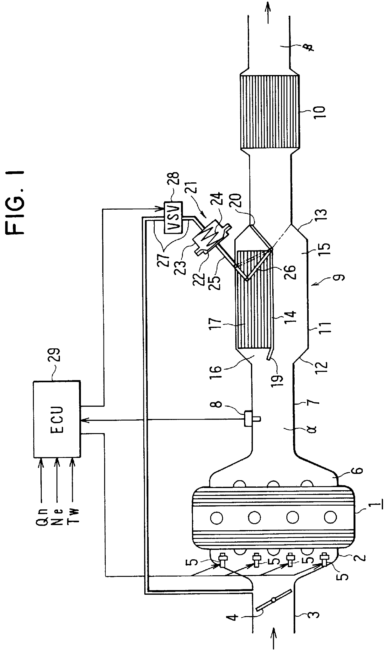
FIG. 1 is a schematic diagram showing the whole structure of an engine exhaust gas purifying system according to the first embodiment. The engine is mounted in a car.

An intake pipe 3 is connected to the four-cylinder gasoline engine 1 via an intake manifold 2. A throttle valve 4 is disposed within the intake pipe 3. Injectors (fuel injection valves) 5 are disposed at intake ports of the respective cylinders of the engine 1.

An exhaust pipe 7 is connected to the engine 1 via an exhaust manifold 6. An 02 sensor 8 is provided in the exhaust pipe 7. Disposed on the downstream side of the 02 sensor 8 in the exhaust pipe 7 are an adsorption unit 9 and a tertiary catalyst 10.

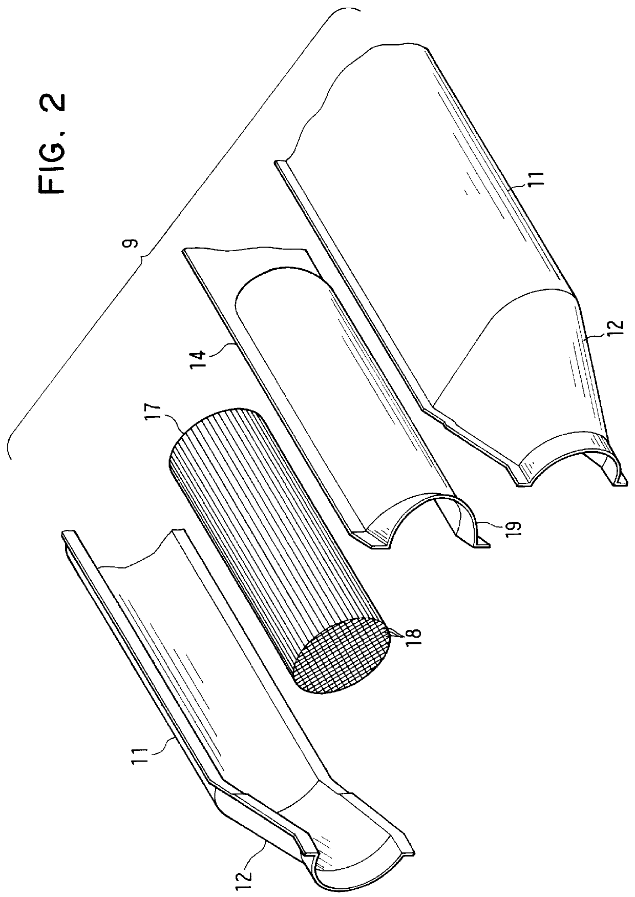
The adsorption unit 9 will be explained below in detail. FIG. 2 is an exploded perspective view of the adsorption unit 9. As shown in FIGS. 1 and 2, the adsorption unit 9 has a cylindrical housing 11 whose diameter is larg...

second embodiment

A second embodiment of the present invention will be explained below centering on a point different from the first embodiment.

Because the whole structure thereof is the same as that shown in FIG. 1, its explanation will be omitted here.

A major difference from the first embodiment described above is in control processing of the ECU 29. Specifically, in the second embodiment, a cooling state of the catalyst 10 is estimated during the desorption process and the change-over valve 20 is repeatedly opened / closed in order to maintain the activated state of the catalyst.

While the adsorption process is the same with that shown in FIG. 3, the desorption process which follows thereto is different. The desorption process of the present embodiment will be explained by using flow diagrams shown in FIGS. 9, 10 and 11. FIG. 12 is a timing chart for explaining the operation of the second embodiment.

When the desorption process starts, the ECU 29 causes exhaust gas to flow through the adsorbing member...


PUM


Abstract

Exhaust gas is caused to flow through a bypass passage during an adsorption mode. At this time, an adsorbing member adsorbs harmful components, e.g. HC, of the exhaust gas. Also, exhaust gas is caused to flow through the bypass passage to thermally desorb the harmful component held at the adsorbing member during a desorption mode. A quantity of heat given from exhaust gas to the adsorbing member during the desorption mode is calculated based on an operation state of an engine. It is determined that the desorption of the harmful components has been finished when the quantity of heat given to the adsorbing member reaches a total quantity of heat required for totally desorbing the harmful components adsorbed by the adsorbing member.

Description

CROSS REFERENCE TO RELATED APPLICATIONThis application is based upon and claims the benefit of priority of Japanese Patent Application No. H.9-131361 filed on May 21, 1997, the contents of which are incorporated by reference.BACKGROUND OF THE INVENTION1. Field of the InventionThe present invention relates to an engine exhaust gas purifying system.2. Description of Related ArtAs a system for purifying exhaust gas of a car engine, there is a catalytic converter system for purifying HC, CO, NOx and the like in exhaust gas by an oxidation reaction or an oxidation-reduction reaction, in which a carrier carrying noble metal such as platinum and rhodium as a catalyst is provided within an exhaust pipe.In the catalytic converter system, the catalyst needs to be heated up to its activation temperature, e.g. 300.degree. C. to 400.degree. C. or more, to purify exhaust gas. However, it has had a problem that because it adopts a method of heating the catalyst by exhaust gas in general, the catal...

Claims


Application Information

Patent Timeline
IPC IPC(8): B01D53/94F01N3/08F01N7/02F01N7/00F01N3/18F01N3/24F01N9/00F01N13/02
CPCB01D53/9454B01D53/9495F01N3/0835F01N3/0878F01N13/009F01N2250/12Y02T10/20Y02T10/22Y02T10/12
Inventor TANAKA, MASAKAZUHODAIRA, KINJISAKAI, TATSUOUSAMI, HIROYUKI
Owner DENSO CORP
Learn More