

Z-axis resistor test system
- Summary
- Abstract
- Description
- Claims
- Application Information
AI Technical Summary
Benefits of technology
Problems solved by technology
Method used
Image

Examples
Embodiment Construction
(S)
1. Field of the Preferred Embodiment(s)
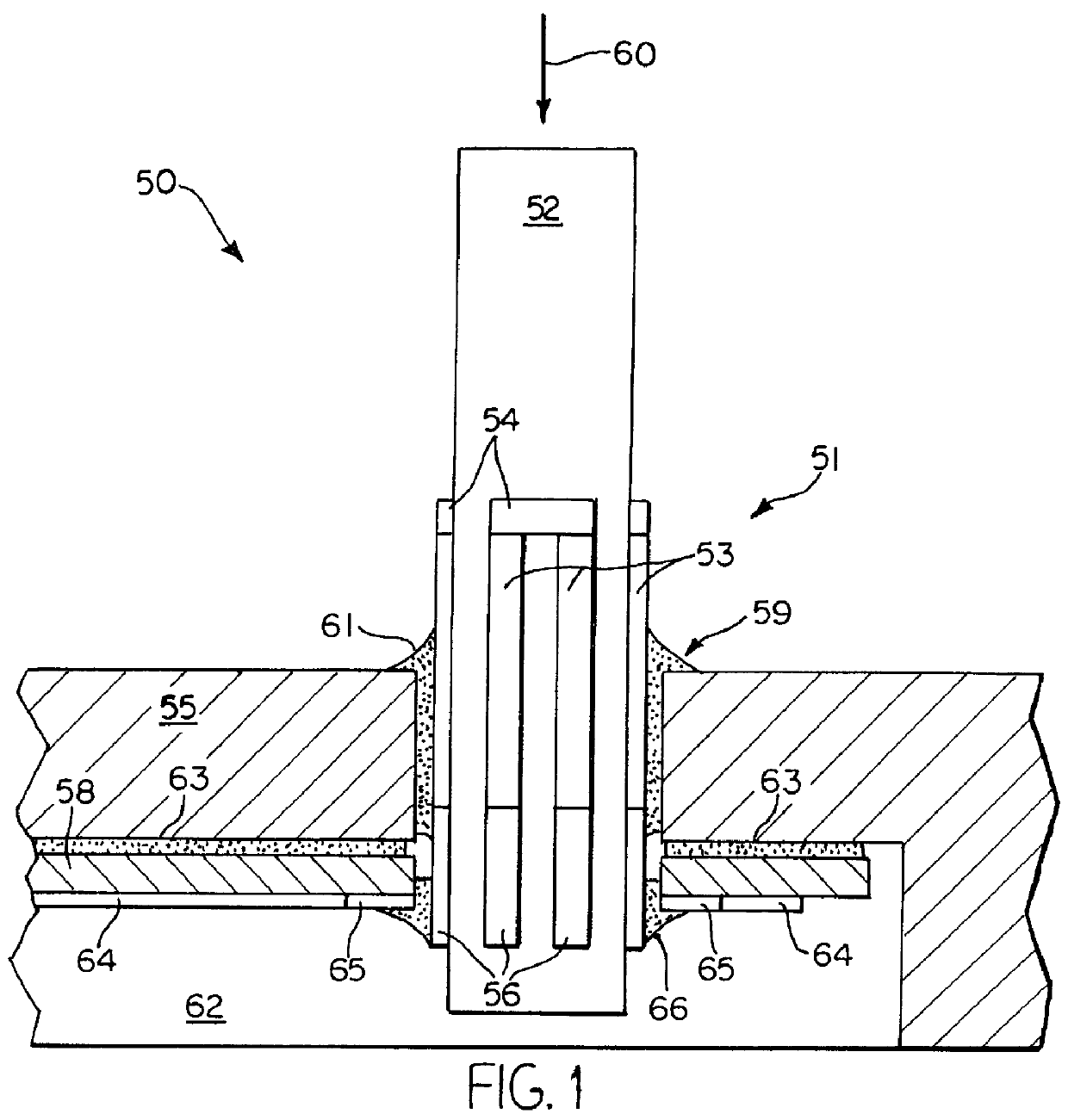
This invention generally relates to the manufacture and testing of resistors. Specifically, there is a test system for z-axis strain gauge resistors on a ceramic substrate used in pointing devices for controlling the positioning, movement and operation of a cursor on a display screen. The z-axis resistors act as the activation button for selecting items on the display screen by tapping on the pointing stick instead of clicking on a mouse button.
2. Description of the Related Art
Various devices are well known for controlling cursor movement over a computer display screen of a computer and for signaling a choice of computer command identified by the position of the cursor on the display screen menu.
Manufacturers of portable laptop computers, recognizing the need for placing the cursor controlling device in a permanent and more convenient location, installed a small stubby, button-like joystick centrally around the keys of the computer keyboard,...
PUM
 Abstract
Description
Claims
Application Information