Hydrodynamic coupling device with a lockup clutch

Inactive Publication Date: 2000-01-25
ZF FRIEDRICHSHAFEN AG
View PDF6 Cites 30 Cited by
  • Summary
  • Abstract
  • Description
  • Claims
  • Application Information

AI Technical Summary

Problems solved by technology

In the hydrodynamic couplings device according to the above-cited application, the hydrodynamic circuit, torsional vibration damper and piston are arranged axially adjacent to one another, resulting in a relatively large axial installation space requirement.
This hydrodynamic coupling device can accordingly be installed, if at all, only with great difficulty, especially in compact automobiles.
Although axial installation space

Method used


Image

  • Hydrodynamic coupling device with a lockup clutch
  • Hydrodynamic coupling device with a lockup clutch
  • Hydrodynamic coupling device with a lockup clutch

Examples


Embodiment Construction

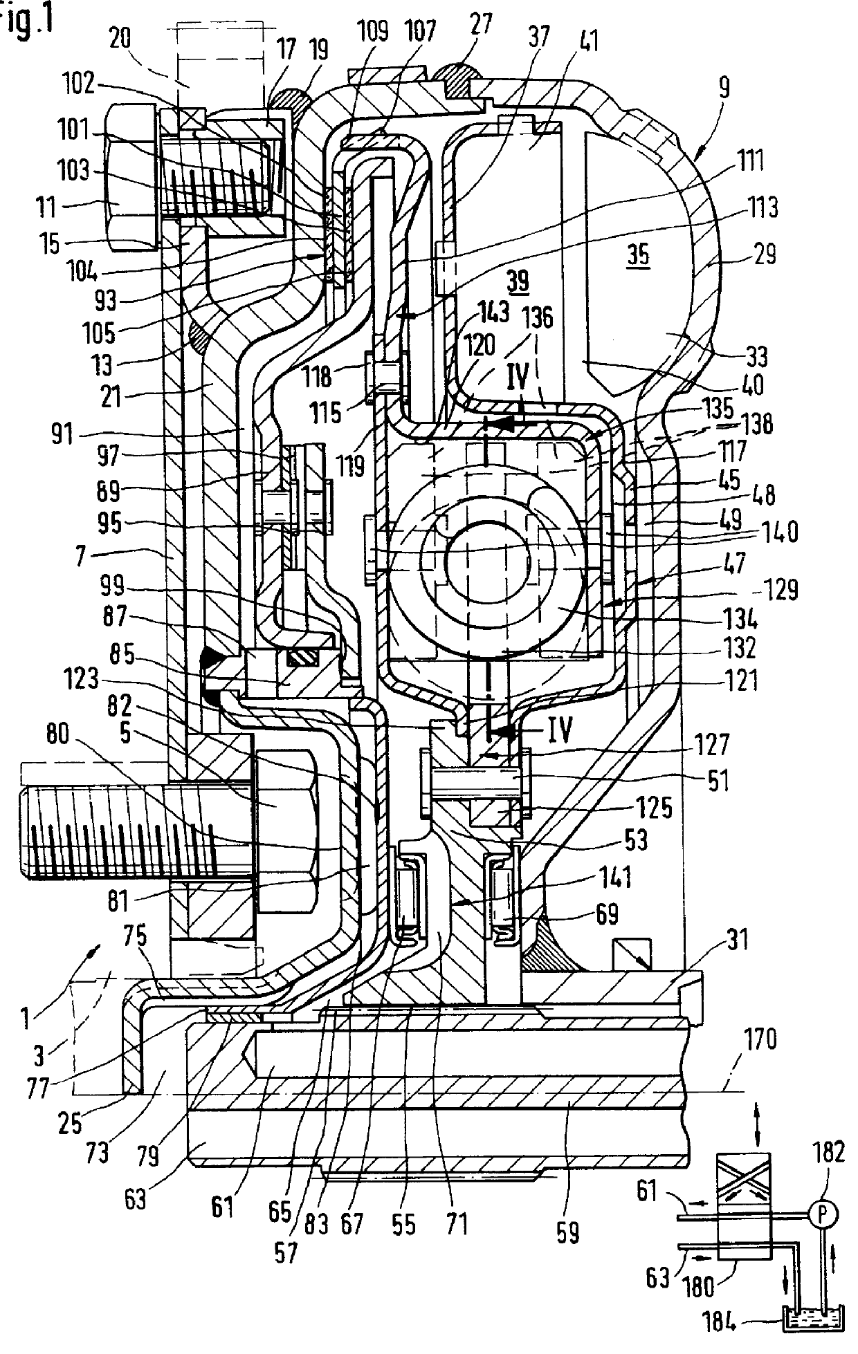
Referring to FIG. 1, a first embodiment of a hydrodynamic coupling device includes an axially flexible plate 7 connected to a clutch housing 9. The plate 7 is fastenable to a drive 1 shown in dashed lines in FIG. 1 such, for example, as an internal combustion engine with a crankshaft 3 by fastening elements 5 in the form of screws which are screwed into threaded bore holes of the crankshaft 3. For connection of the hydrodynamic coupling device to the crankshaft 3, an annular holder 15 is fastened by a weld 13 at a primary flange 21 of the clutch housing 9. The annular holder 15 projects in the direction of the flexible plate 7 and fixedly receives blocks 17. These blocks 17 are fastened, in turn, to the primary flange 21 via a weld 19 and having threaded bore holes for receiving connection means 11. The clutch housing 9 is fastened to the flexible plate 7 via these connection means 11. The annular holder 15, preferably together with the blocks 17, receives a toothed rim 20 so that a...


PUM


Abstract

A hydrodynamic coupling device includes an impeller wheel with an impeller shell and a vane arrangement and a turbine wheel with a turbine shell and vane arrangement. The vane arrangements of the impeller wheel and the turbine wheel form a hydrodynamic circuit. A lockup clutch is constructed with an axially movable piston for transmitting torque by the application of pressure in the direction of a primary flange of a clutch housing via at least one friction facing provided axially between the piston and the primary flange. The lockup clutch has a torsional vibration damper with a drive-side transmission element and a driven-side transmission element which is movable relative to the latter, each of which is provided with driving means for elastic elements. The torsional vibration damper has a damping device that penetrates axially, at least along part of its axial extension, into an annular space that is enclosed by the turbine wheel and at least partially enclosed by the impeller wheel such that the damping device is arranged radially inside of the hydrodynamic circuit. The annular space is formed by an axial bulge of a radial lengthening of the turbine shell. The radial lengthening projects radially inward up to the turbine hub. The axial bulge approaches the side of the clutch housing remote of a drive up to the width of a gap, and this gap has a width which is sufficient to ensure that the turbine wheel can move relative to the clutch housing without contact.

Description

1. Field of the InventionThe invention is directed to a hydrodynamic coupling device with a hydrodynamic circuit having an impeller wheel and a turbine wheel, a lockup clutch, and a torsional vibration damper with a drive-side transmission element and a driven-side transmission element which is movable relative to the latter, each of the transmission elements having driving means for interacting with circumferentially acting elastic elements.2. Description of the Related ArtA prior art hydrodynamic coupling device in the form of a torque converter is disclosed in German reference DE 44 33 256 A1, particularly in FIG. 1, with a hydrodynamic circuit having an impeller wheel, a turbine wheel and a stator wheel. This coupling device further includes a lockup clutch having an axially movable piston and a torsional vibration damper. The piston is movable in the direction of a primary flange of the clutch housing by an overpressure in the hydrodynamic circuit, wherein a plate or blade is p...

Claims


Application Information

Patent Timeline
IPC IPC(8): F16H45/00F16H45/02
CPCF16H45/02F16H2045/0226F16H2045/0231F16H2045/0247F16H2045/0278
Inventor KUNDERMANN, WOLFGANG
Owner ZF FRIEDRICHSHAFEN AG
Why Eureka
Try Eureka