Effect of air baffle design on mottle in solvent coatings

a technology of solvent coating and air baffle, which is applied in the direction of drying machines with progressive movements, lighting and heating apparatus, furnaces, etc., can solve the problems of limiting the speed at which a product can be manufactured, occurrence of mottle, and one of the most common defects of organic solvent coatings

Inactive Publication Date: 2000-02-01
EASTMAN KODAK CO
View PDF6 Cites 27 Cited by
  • Summary
  • Abstract
  • Description
  • Claims
  • Application Information

AI Technical Summary

Problems solved by technology

One of the most common defects associated with organic solvent coatings is mottle.
Direct impingement air can cause mottle by disturbing the coating.
Even if coatings are allowed to dry without direct air impingement, the shear forces caused by the web moving through still air can cause mottle.
This will limit the speed at which a product can be manufactured.
The occurrence of mottle is often cited as the single greatest limitation to productivity improvement in the drying of coated webs.
Coatings can be made to be more robust to mottle by increasing the viscosity of the solutions and decreasing the wet thickness of the coating (concentrating the solution) such as described in Miller, C. A. and Neogi, P.; "Interfacial Phenomena"; Marcel Decker; 1995 but, this is not always possible because of coatability or solution stability concerns.
Even if the pressure and shear forces are not great enough to blow the coating around, non-uniformities in the air velocity impinging on the coating can cause surface tension driven flow.
Non-uniform air flow can cause local variations in heat and mass transfer rates which in turn cause concentration and temperature variations.
This design does not employ air baffles and has the disadvantage that the fan must be located a fixed distance from the coater and this may itself represent a speed limitation since the coating must be "dry" by the time it passes the fan or the non-uniform air flow that exists there may cause mottle.
In 1992, Hella and Buchanan, U.S. Pat. No. 5,105,562, described a ventilating and impinging air bar assembly primarily for improved conveyance but, this design relies on direct front side air impingement which is, in general, not desirable from the standpoint of minimizing mottle.
Using this technique, mottle occurs in the coating.
Too large of a vertical component and the coating could be disturbed.

Method used


Image

  • Effect of air baffle design on mottle in solvent coatings
  • Effect of air baffle design on mottle in solvent coatings
  • Effect of air baffle design on mottle in solvent coatings

Examples


Embodiment Construction

In this work, five different air baffle designs were evaluated experimentally to see their effect on mottle. These designs vary greatly in the character of air flow they produce near the web. The next section describes these air baffles and the experimental run. This is followed by experimental results.

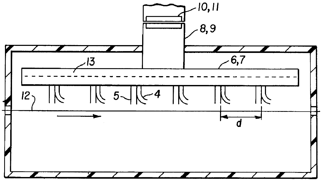
In order to examine the effect of air baffle geometry on the level and character of mottle in solvent coatings, a total of five different air baffles were built and tested. These are shown in FIG. 4. Design d is a commercially available nozzle.

The slot and extended slot designs supply air normal to the web while the V-channel is specifically designed to feed air to the chamber with very little direct impingement onto the coating. The commercially available and arced designs are capable of delivering both normal and parallel air flows. The main difference between the commercially available design and arced slots are that the arced slots provide less than parallel air flow in one direct...


PUM


Abstract

Apparatus for drying coated web material and preferably moving web material comprises a nozzle, means for supplying air to the nozzle and means to distribute the air through said nozzle substantially uniformly across the web width, said nozzle arcing from a position perpendicular with respect to the plane of the web to a position substantially parallel with respect to the plane of the web, said nozzle having an exit slot wherein the air is discharged from the exit slot at an angle of between 1 DEG and 45 DEG with respect to the plane of the web.

Description

This relates to apparatus and method for drying coated webs and, more particularly to the drying of mottle sensitive coatings on film base such as photographic film and paper.BRIEF DESCRIPTION OF THE PRIOR ARTOne of the most common defects associated with organic solvent coatings is mottle. Direct impingement air can cause mottle by disturbing the coating. Also, the heat transfer uniformity is critical. Local variations in heat transfer will show up as mottle. Even if coatings are allowed to dry without direct air impingement, the shear forces caused by the web moving through still air can cause mottle. This will limit the speed at which a product can be manufactured. The occurrence of mottle is often cited as the single greatest limitation to productivity improvement in the drying of coated webs. In order to produce acceptable coatings, web speeds are often reduced significantly from what the machine is capable of coating and drying.Mottle patterns can range from random and blotchy...

Claims


Application Information

Patent Timeline
Patent Type & Authority Patents(United States)
IPC IPC(8): F26B13/10F26B21/00F26B13/04
CPCF26B13/10F26B21/004
Inventor BELL, BRENT C.CLINE, JR., GEORGE M.KLASNER, CHRISTOPHER J.
Owner EASTMAN KODAK CO
Why Eureka
Try Eureka