Process for oxidative exhaust gas cleaning

a technology of oxidative exhaust gas and cleaning process, which is applied in the direction of gas treatment, organic chemistry, using liquid separation agent, etc., can solve the problems of reintroduction of filtered exhaust air back into the filtered exhaust air, the need to dispose of the residuals of the filter unit and the separating unit, and the difficulty of cleaning requirements

Inactive Publication Date: 2000-02-01
JENOPTIK KATASORB
View PDF4 Cites 24 Cited by
  • Summary
  • Abstract
  • Description
  • Claims
  • Application Information

AI Technical Summary

Benefits of technology

A small part of the feed air enters the reactor I through valve 6, which reactor 1 then assumes the state of an oxidizer. The reaction zone 10 located at the output of the reactor is brought to the catalyst light-off temperature by means of its heater. When this temperature is reached, the preceding reaction zones are activated in sequence by their associated heaters. By adapting the catalyst and adsorption mass, a significant quantity of pollutant is first desorbed in the neighborhood of the catalyst light-off temperature and is decreased by oxidation at the respective next catalyst layer. As a result of the developed reaction heat, autothermal operation of the catalyst is ensured until combustion of the entire store of pollutant. The heaters are therefore switched off after the catalyst light-off temperature is reached. After the reduction of all of the pollutants capable of desorption, the temperature of the reactor 1 gradually drops to the ambient temperature.
After a sufficient cooling period, the setting of the valves 6 and 7 is changed by program control. The charged reactor 2 now operates as an oxidizer, whereas reactor 1 acts as an adsorber. All processes are repeated in a corresponding manner.
The invention will be explained in still more detail hereinafter with the aid of the following examples.

Problems solved by technology

For this reason, exhaust installations of this type often contain costly air-to-air heat exchangers or else the heat is supplied subsequently by additional heating of the air supply.
For the most part, the residues of the filter units and separating units must be disposed of as special waste in a costly manner.
In the case of exhaust gases containing toxic pollutants, it is generally not possible to reintroduce the filtered exhaust air back into the workplace, since there are hardly any economically feasible solutions for safely removing pollutants with an adequate cleaning effect.
Cleaning requirements are especially difficult when the separated residue has multiple phases and its solid phase has a sticky, pasty consistency.
In general, external heating of the exhaust air for the purpose of achieving and maintaining the working temperature of the catalyst is uneconomical.
Where the elimination of unacceptable concentrations of pollutants with respect to work hygiene is concerned, a concentration sufficient for the autothermal catalyst operation is never achieved.
A further disadvantage in the known arrangements and processes consists in that a cleaning efficiency allowing the exhaust air to be reintroduced into the workplace is achieved only by the most elaborate combinations of processes.
In such cases, washing liquids or solid filter auxiliary materials are needed, which further increases the quantity of special waste generated.

Method used


Image

  • Process for oxidative exhaust gas cleaning
  • Process for oxidative exhaust gas cleaning

Examples


2nd embodiment example

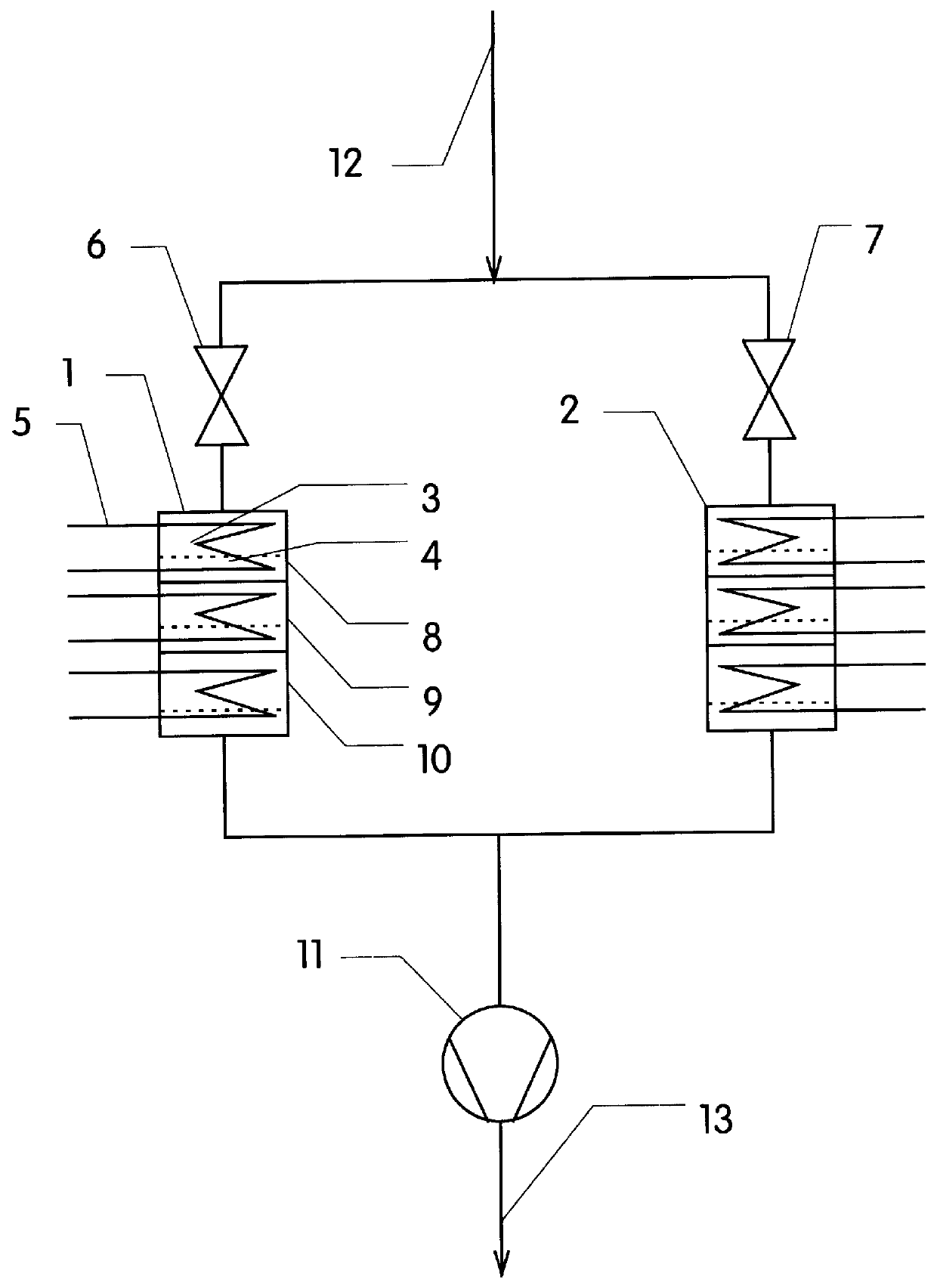
An experimental arrangement with a throughput of 1500 m.sup.3 / h was designed for use for treating oil mists in workshop rooms. An oxidation exhaust gas cleaning means in compact constructional form was realized for treating this air. The entering room air is distributed to the reactors by means of a motor-operated rotary slide in the upper part of the reactor. The rotary slide is so designed that, in both end positions, 20 m.sup.3 / h of air flow through the reactor operating as an oxidizer. The pressure loss in the reactor in the adsorber operating mode was 4380 Pa.

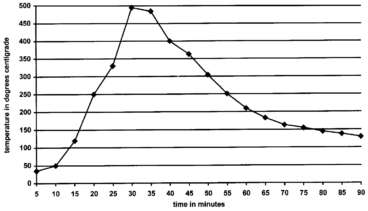
The reactors are formed, in each instance, of a mixture of 21 l of a commercial wire catalyst and 5 l of HZSM catalyst distributed to 2 reaction zones. The free cross-sectional area through which the flow of air passes is 0.04 m.sup.2. The heating is suitable for catalyst light-off temperatures up to a maximum of 450.degree. C. The adjusted time delay between the start of activation of the two reaction zones was 8 min. T...


PUM

PropertyMeasurementUnit
pressure lossaaaaaaaaaa
light-off temperatureaaaaaaaaaa
light-off temperaturesaaaaaaaaaa

Abstract

A process is provided for destroying organic contaminants, such as oil mists from workshop rooms, formaldehyde and aromatics, out of exhaust gases by passing the exhaust gas through two reactors connected in a parallel arrangement to a contaminated exhaust gas inlet. Each of the two reactors is equipped with a plurality of serially arranged reaction zones, wherein each reaction zone contains an upstream catalyst (such as a commercial wire knit catalyst); a downstream absorbent (such as Y zeolite or H-ZSM) and a heater. A major portion of the contaminated exhaust gas is passed through one of the two reactors, while, simultaneously, a minor portion of the contaminated exhaust gas is passed through the other reactor. After a period of time, the exhaust gas flow rate through the two reactors is reversed so that a major portion of the exhaust gas now flows through the reactor that previously had a minor portion of the exhaust gas flowing through it and a minor portion of the exhaust gas now flows through the reactor that previously had a major portion of the exhaust gas flowing through it, so that the process is cyclical in this manner. When a major portion of the exhaust gas flows through a reactor, the hydrocarbon contaminants are sorbed into the absorbent. When a minor portion of the exhaust gas flows through a reactor, the reactor is heated to the catalyst light-off temperature so that the contaminants within the exhaust gas and the contaminants released from the absorbent are catalytically destroyed in a downstream catalyst in an adjacent downstream reaction zone.

Description

a) Field of the InventionThe invention is directed to an arrangement and to the associated process for cleaning exhaust gases with oxidizable pollutants in which even small concentrations of pollutants can be safely reduced through the combination of adsorption and catalysis with low expenditure of energy. The invention is further directed to the development of the process as a regenerative principle.b) Description of the Related ArtA large number of modern processes for the treatment and processing of polymer materials and the melting losses or burnup of oils and other process materials in metalworking generate polluted exhaust air that is usually removed from the workplace by means of plant exhaust installations or localized exhaust systems in order to maintain work hygiene standards. Similar exhaust installations are used in kitchen facilities to remove steam or vapor especially when foodstuff is being prepared by frying in oils and fats.All known processes have in common that a ...

Claims


Application Information

Patent Timeline
Patent Type & Authority Patents(United States)
IPC IPC(8): B01D53/04B01D53/86
CPCB01D53/0438B01D53/0454B01D53/8668B01D53/869B01D53/0446B01D2257/70B01D2259/40003B01D2259/4146
Inventor HAUPT, JENS
Owner JENOPTIK KATASORB
Why Eureka
Try Eureka