Rotatable dynamic seal and guide for a medical obstruction treatment device sub-assembly coupled to a drive motor unit

a technology of dynamic seal and guide, which is applied in the field of rotating seal mechanism, can solve the problems of difficult to fabricate effective seals, undesirable rotation, and not always possible to know in advance just how to opera

Inactive Publication Date: 2000-02-08
TYCO HEALTHCARE GRP LP
View PDF24 Cites 106 Cited by
  • Summary
  • Abstract
  • Description
  • Claims
  • Application Information

AI Technical Summary

Benefits of technology

and the objects, advantages and features thereof have been presented here simply to point out some of the ways that the invention overcomes difficulties presented in the prior art and to distinguish the invention from the prior art and is not intended to operate in any manner as a limitation on the interpretation of claims that are presented initially in the patent application and that are ultimately granted.

Problems solved by technology

In practice, the guidewire and microcatheter O.D. and the drive shaft lumen I.D. are closely dimensioned, and it is difficult to fabricate such seals that function effectively.
At this point, the brush delivery catheter and brush drive shaft are extended through the patient's vascular system and it is undesirable to rotate them within the vascular system.
It is not always possible to know in advance just how the drive motor unit will be aligned with respect to the side port of the Y-connector when the attachment is finished.
However, in use, blood and thrombolytic agent backflows proximally through the brush drive shaft lumen and can infiltrate the drive motor unit and cause it to fail.

Method used


Image

  • Rotatable dynamic seal and guide for a medical obstruction treatment device sub-assembly coupled to a drive motor unit
  • Rotatable dynamic seal and guide for a medical obstruction treatment device sub-assembly coupled to a drive motor unit
  • Rotatable dynamic seal and guide for a medical obstruction treatment device sub-assembly coupled to a drive motor unit

Examples


Embodiment Construction

In view of the apparent interchangeable use in the background art, only the terms "soft obstruction" or "thrombus" and "thrombectomy" will be employed in the following description of the preferred embodiment of the invention, and it will be understood that these terms shall embrace and be the equivalent of blood clot or embolus and embolectomy, respectively, and are applicable to the removal of soft, recently formed emboli, thrombi or blood clots.

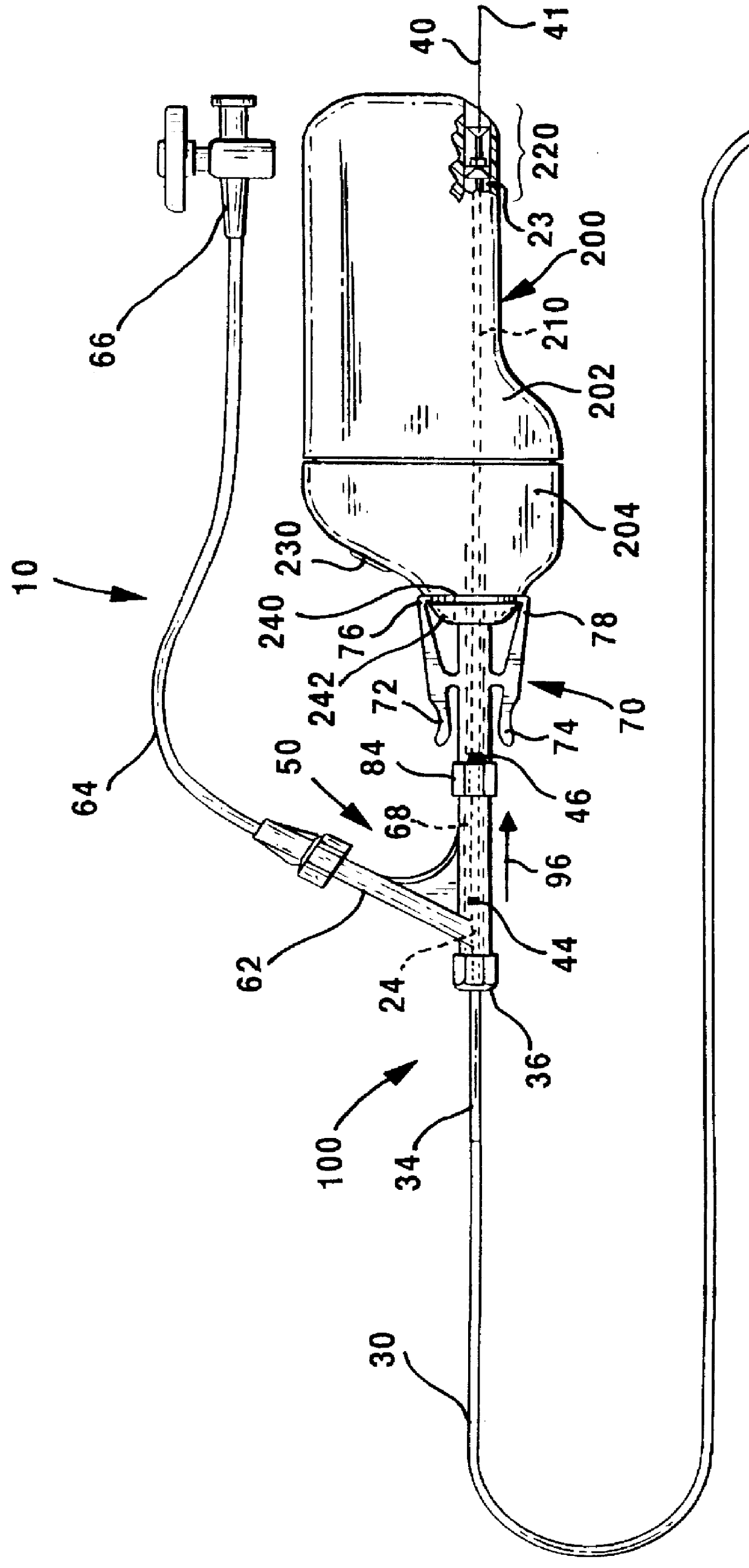
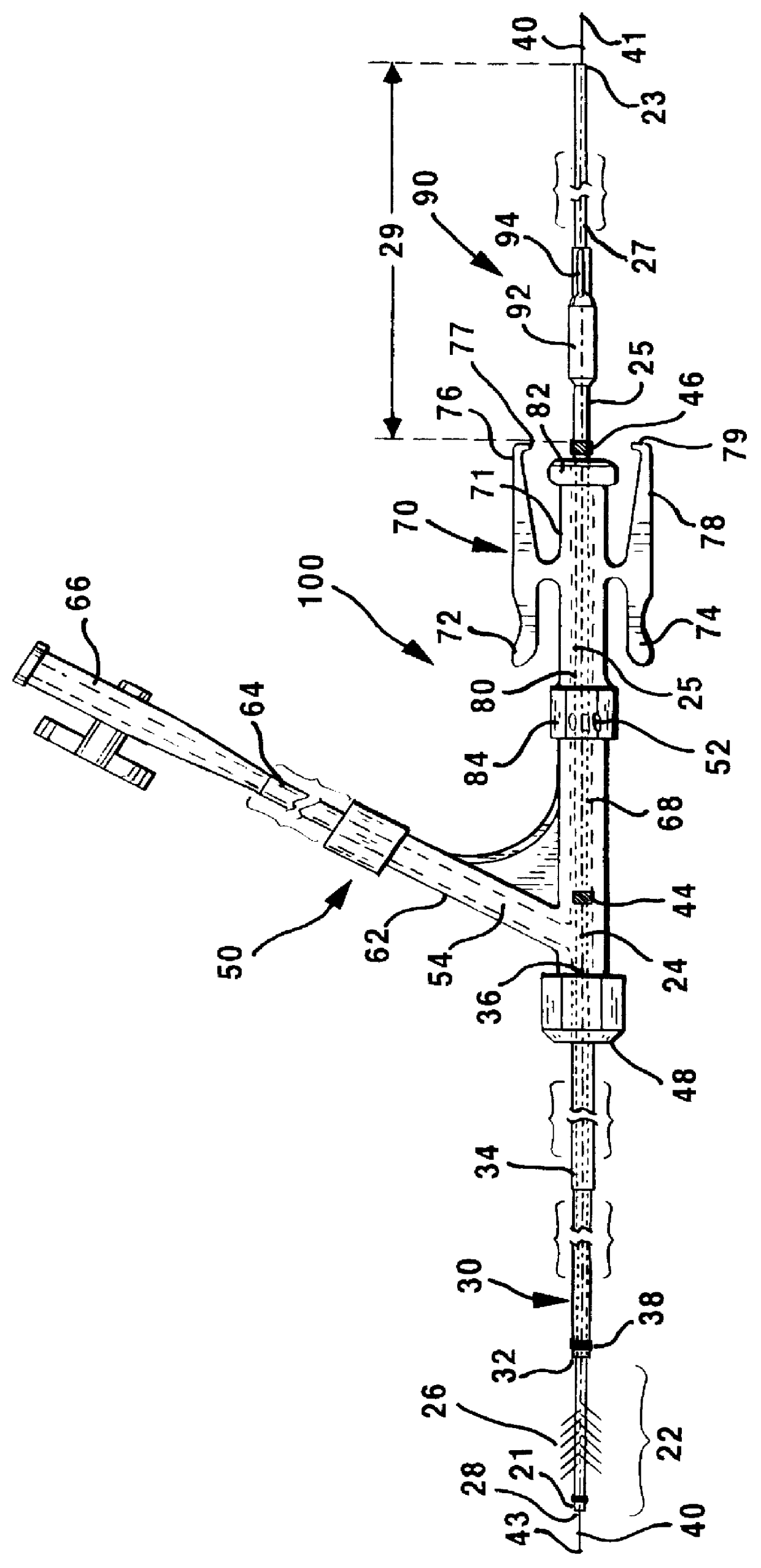
FIG. 1 illustrates a motor and brush assembly 10 which incorporates one embodiment of a dynamic seal assembly 220 for sealing the interior of a drive motor unit 200 from the backflow of blood and thrombolytic agent through a hollow lumen brush drive shaft 20 when the brush sub-assembly 100 is attached with the drive motor unit 200. The dynamic seal assembly 220 allows rotation of the brush drive shaft with respect to the drive motor unit 200. Moreover, it is located in and forms part of a drive motor lumen 210 that is formed with proximal a...


PUM


Abstract

A miniaturized obstruction treatment device, e.g., a brush, particularly adapted for medical use formed at the distal end of an elongated brush drive shaft having a hollow lumen formed therein for introduction over a guidewire. The brush drive shaft is enclosed in the lumen of an brush delivery catheter, and the brush bristles of the distal brush are adapted to be garaged in a distal end section of the brush delivery catheter lumen. A Y-connector and an brush sub-assembly connector are attached to the proximal end of the brush delivery catheter and form an brush sub-assembly with the brush drive shaft and brush. The Y-connector allows infusion of thrombolytic agents into the brush delivery catheter lumen for emission at the distal end opening thereof adjacent the brush. In use, the brush sub-assembly connector connects the brush sub-assembly with a drive motor unit connector of a drive motor unit. The drive motor unit receives the proximal end of the drive shaft and rotates it to rotate the brush bristles. The brush and brush drive shaft distal section are automatically extended out of the catheter lumen distal end opening when the sub-assembly connector and the drive motor unit connector positively lock together. Simultaneously, a drive hub of the brush drive shaft locks into a drive chuck of a drive motor unit to enable rotation of the drive shaft, and the proximal drive shaft end is seated in a dynamic seal that inhibits infiltration of blood and thrombolytic agent into the drive motor housing.

Description

1. Field of the InventionThe present invention relates to the assembly of a drive motor unit with an obstruction treatment device sub-assembly particularly adapted for medical use and more particularly to a rotatable seal mechanism for sealing a drive motor unit from infiltration of blood and thrombolytic agent that backflows through the lumen of a hollow drive shaft inserted into a drive motor lumen and guiding means for guiding guidewires or other elongated medical devices through the drive motor unit lumen.2. Description of the Background ArtCommonly assigned, U.S. Pat. No. 5,370,653 to Cragg, incorporated herein by reference in its entirety, discloses a thrombectomy system for dissolving a soft fibrinous obstruction, such as a recently formed thrombus, within a patient's vascular system, either in a patent vein or artery or in a vascular implant, e.g. an A / V graft. The thrombectomy system employs rotating brush bristles within the thrombus to separate the fibrin of the thrombus ...

Claims


Application Information

Patent Timeline
Patent Type & Authority Patents(United States)
IPC IPC(8): A61B17/22A61B17/32A61B17/00
CPCA61B17/320758A61B2017/0046A61B2017/320012
Inventor WALKER, BLAIR D.POOL, SCOTT L.
Owner TYCO HEALTHCARE GRP LP
Why Eureka
Try Eureka