Method and apparatus for a process and project management computer system

a project management and project technology, applied in the direction of electric programme control, total factory control, instruments, etc., can solve the problems of unassigned resources, idle project workers, and work that should require an amount of effort worth managing

Inactive Publication Date: 2000-02-08
IBM CORP
View PDF10 Cites 248 Cited by
  • Summary
  • Abstract
  • Description
  • Claims
  • Application Information

AI Technical Summary

Benefits of technology

NULL tasks may be declared in cases where split navigation conditions select between several possible threads, eliminating the execution for non selected threads. The FALSE propagation by the workflow manager IBM FlowMark takes care to promote TRUE / FALSE values also through dead threads. Since a "select n of m outputs" split, as defined above, can only be followed by a composite task, it will be the decision of the planner who resolves the composite task, whether he resolves the task for execution, or declares the task and, where applicable, its successors to NULL, in which case it will be ignored for scheduling and resource allocation mechanisms. A more elaborate architecture may also automate the definition and propagation of NULL assignments automatically, if the workflow manager provides application program interfaces (APIs) for the interrogation of control connectors about their current state.

Problems solved by technology

The units of work should require an amount of effort worth managing for the enterprise.
Incomplete planning would lead to unassigned resources and an idle workforce in the project.
These dynamic boundaries complicate the implementation of these views to some extent, but are a requirement of reality in projects of sufficient size and duration where static definitions and resource allocation at project start are not achievable and not realistic.

Method used


Image

  • Method and apparatus for a process and project management computer system
  • Method and apparatus for a process and project management computer system
  • Method and apparatus for a process and project management computer system

Examples


Embodiment Construction

One preferred embodiment of a method for process and project management according to the present invention will be described in the following with reference to the accompanying drawings.

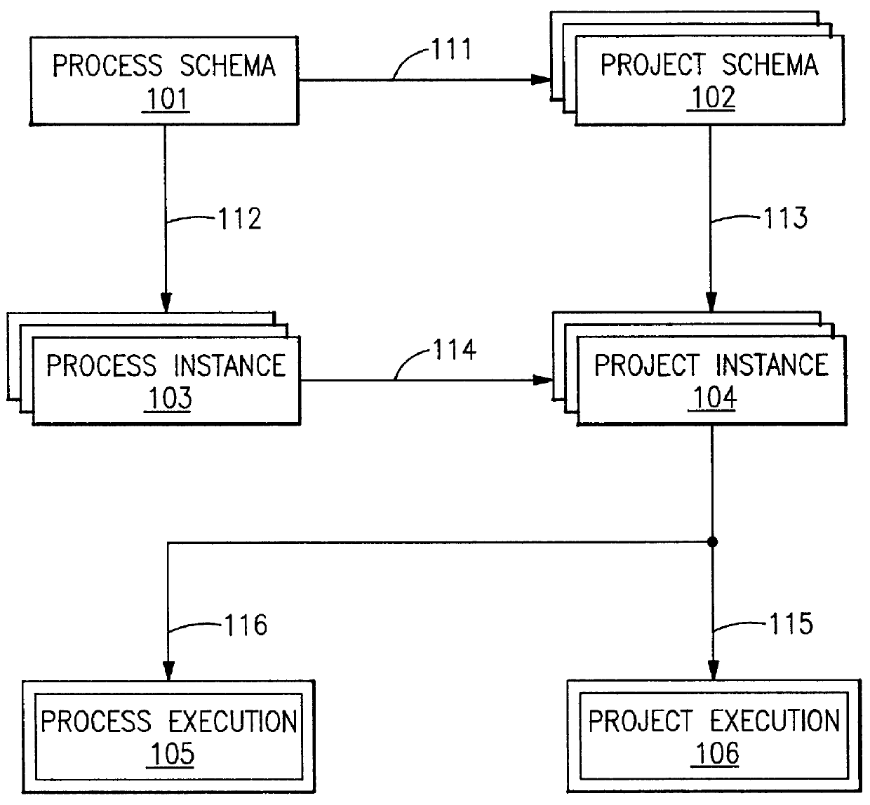
The FIG. 1 shows a sequence of schemas and instances and shows how the work process object (WPO) evolves in the stages of:

process schema 101,

project schema 102,

process instance 103,

project instance 104,

project instance gross (containing composite tasks),

project instance executable (containing simple tasks),

process instance executed 105, and

project instance executed 106.

From the process schema 101, project schemas 102 are derived 111 and process instances 103 are derived 112 as shown in FIG. 1 according to the used reference signs. Project instances 104 are derived 113 from the project schemas 102 and also are derived 114 from the process instances 103. The project instances 104 are the basis 116 for process execution 105 and are the basis for project execution 106.

Each stage is populated by a domain,...


PUM


Abstract

PCT No. PCT/EP95/03289 Sec. 371 Date Dec. 10, 1998 Sec. 102(e) Date Dec. 10, 1998 PCT Filed Aug. 18, 1995 PCT Pub. No. WO97/07472 PCT Pub. Date Feb. 27, 1997The inventive concept comprises a system platform for a synergistic, role modular work process environment. A work process object (WPO) (1001) is created, residing in a data base, and stored in a memory of the process and project management computer system (1030). All data concerning the process and project management are reported to said work process object (WPO) (1001) and said work process object (WPO) (1001) is used as a common data base. According to the inventive concept, each view must be supported by a specific workplace, represented by digital data and enforcing the rules for the specific role. A work process information model supports the dynamic definition and use of a data base object representing a work process, boch in its process and project planning modes and its execution. According to the inventive concept, one object supports simultaneously all modes delimited by dynamically moving boundaries. Workplace implementation enforces over-all rules for each role in the inventive system.

Description

The present invention generally relates to the technical field of computer based process and project management and to process and project management computer systems. More specifically, the present invention relates to a method and a system for providing process and project management on a common management computer system.The process of designing, developing and manufacturing a new product and the process of changing or adapting an existing product presents many challenges to product managers and engineers to bring the product to market for the least cost and within schedule while maintaining or even increasing product quality. Many companies are realizing that the conventional product design process is not satisfactory to meet these needs. They require early involvement of manufacturing engineering, cost engineering, logistic planning, procurement, manufacturing, service and support with the design effort. Furthermore, they require planning and control of product data through des...

Claims


Application Information

Patent Timeline
Patent Type & Authority Patents(United States)
IPC IPC(8): G06Q10/00G06F9/06G05B19/418G06Q10/06
CPCG06Q10/06Y10S707/99943Y10S707/99942Y02P90/02
Inventor LEISTEN, UDOVOESCH, EKKEHARDPARNCUTT, GEOFFBANDAT, KURT
Owner IBM CORP
Why Eureka
Try Eureka