Vehicle tire with a tread exhibiting sipes substantially running in the axial direction

a technology of axial rotation and tire, applied in the field of vehicle tires, can solve the problems of poor snow performance, high surface friction expected of summer tires, and oblique positioning of bridge ends that affect the braking path on wet roads,

Inactive Publication Date: 2000-02-22
CONTINENTAL AG
View PDF8 Cites 43 Cited by
  • Summary
  • Abstract
  • Description
  • Claims
  • Application Information

AI Technical Summary

Benefits of technology

According to the present invention, the terminal end bending is further reduced, thus, improving the wet and dry braking efficiency, while the number of sipes and the shape of the sipes, when viewed from the top or perpendicular to the tread surface, remains unchanged. Traction and braking efficiency, however, are not decreased on packed snow and ice because the slight terminal end bending that is required for creating the edges still occurs, as in the prior art, with the exertion of very small tangential forces.
To produce tires in accordance with the present invention, the unvulcanized (unfinished) tire does not have to be changed. However, different vulcanization molds are required. In accordance with the present invention, metal sheets for the sipes have to be anchored in conventional vulcanization molds and have to provide corrugated ridges and valleys that are oriented at an angle with respect to a metal anchor edge. Instead of first punching and then bending the corrugation, the present invention, due to the angled positioning of the corrugated ridges and valleys and the different lengths of the individual corrugated ridges and valleys in the area of the edges associated therewith, first bends larger sheets of metal into the desired corrugated manner parallel to the edges of the sheet metal mold, and then separates out the individual sipe metal sheets, which are oriented at an angle to the edges of the sheet metal mold, e.g., by using a punching method.

Problems solved by technology

However, it has been found that the oblique positioning of the bridge ends has a negative effect on the braking path on wet roads.
This disadvantage is particularly unfortunate for modem winter tires, because it is important to achieve not only good traction on snow but good braking performance on wet roads.
Even on dry roads, a high degree of surface friction is expected of summer tires.
However, this results in a poorer performance on snow.
However, the main effect of the prior art is that a very small end rotation is effective for improving the traction on snow and ice, but does not have a significant impact on the braking on a wet or dry road, and a larger terminal end rotation increases the traction on snow and ice only to an insignificant degree, but would decrease the braking performance on wet and dry surfaces significantly.
Traction and braking efficiency, however, are not decreased on packed snow and ice because the slight terminal end bending that is required for creating the edges still occurs, as in the prior art, with the exertion of very small tangential forces.

Method used


Image

  • Vehicle tire with a tread exhibiting sipes substantially running in the axial direction
  • Vehicle tire with a tread exhibiting sipes substantially running in the axial direction
  • Vehicle tire with a tread exhibiting sipes substantially running in the axial direction

Examples


Embodiment Construction

The particulars shown herein are by way of example and for purposes of illustrative discussion of the preferred embodiments of the present invention only and are presented in the cause of providing what is believed to be the most useful and readily understood description of the principles and conceptual aspects of the invention. In this regard, no attempt is made to show structural details of the invention in more detail than is necessary for the fundamental understanding of the invention, the description taken with the drawing figure making apparent to those skilled in the art how the invention may be embodied in practice.

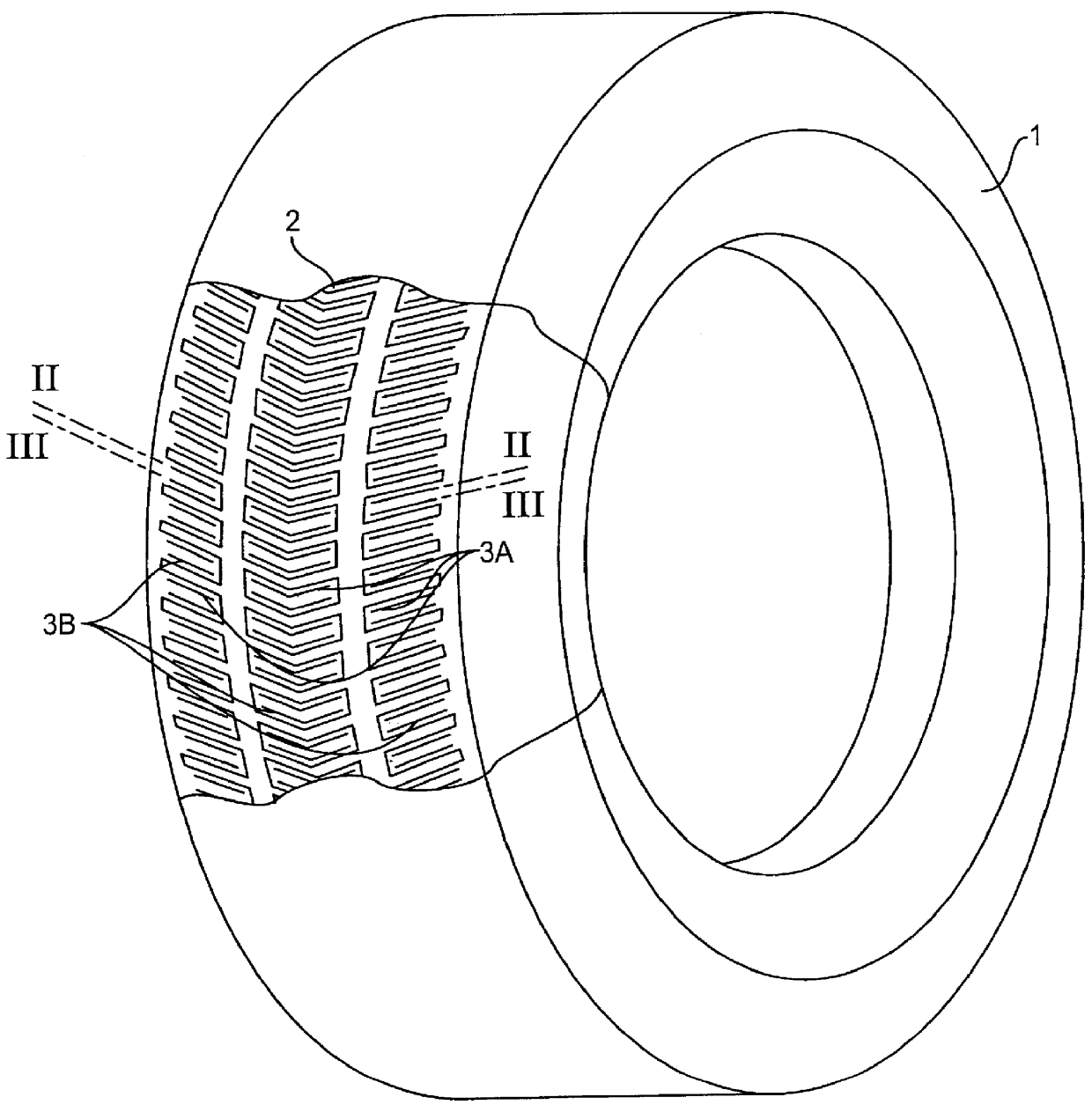
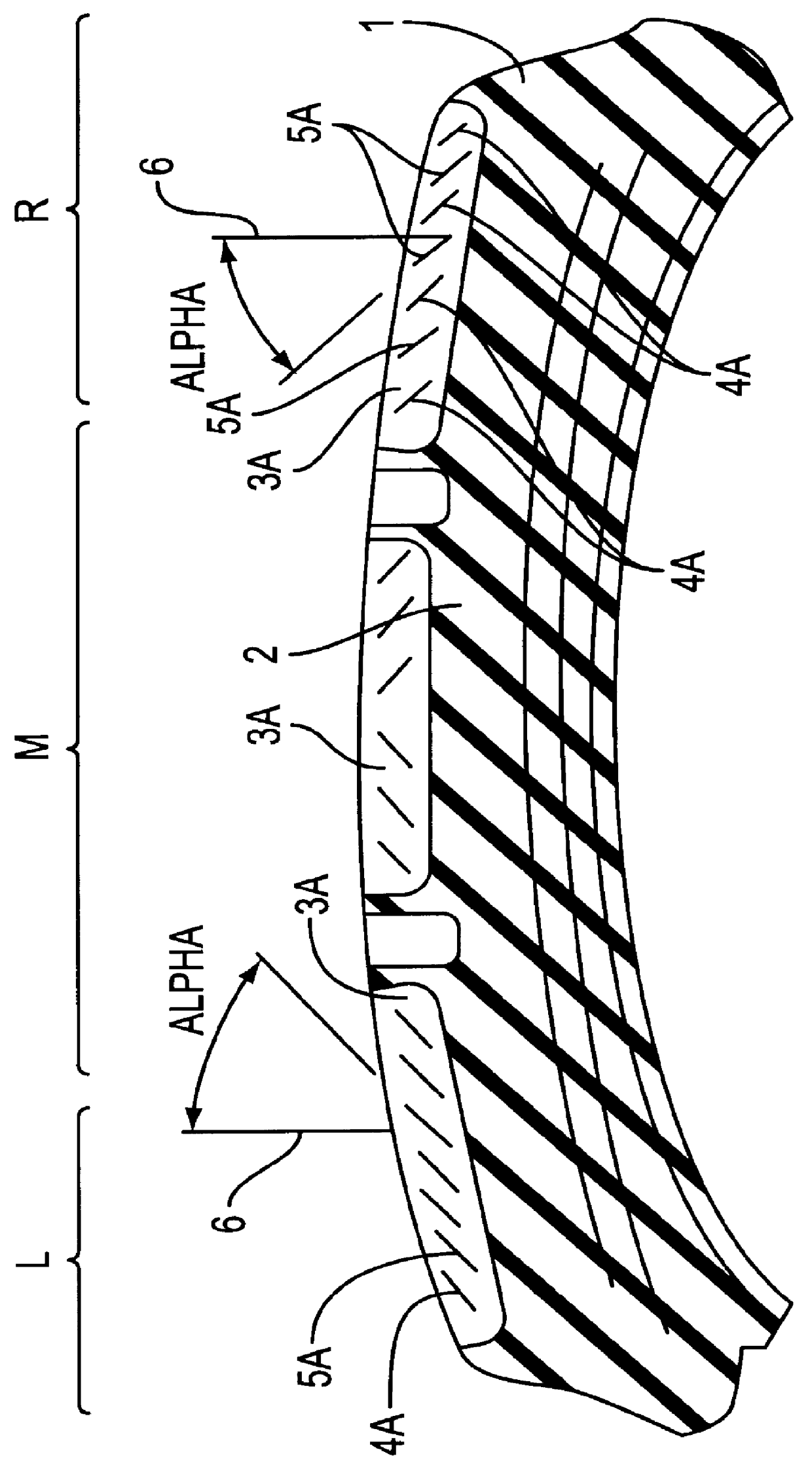
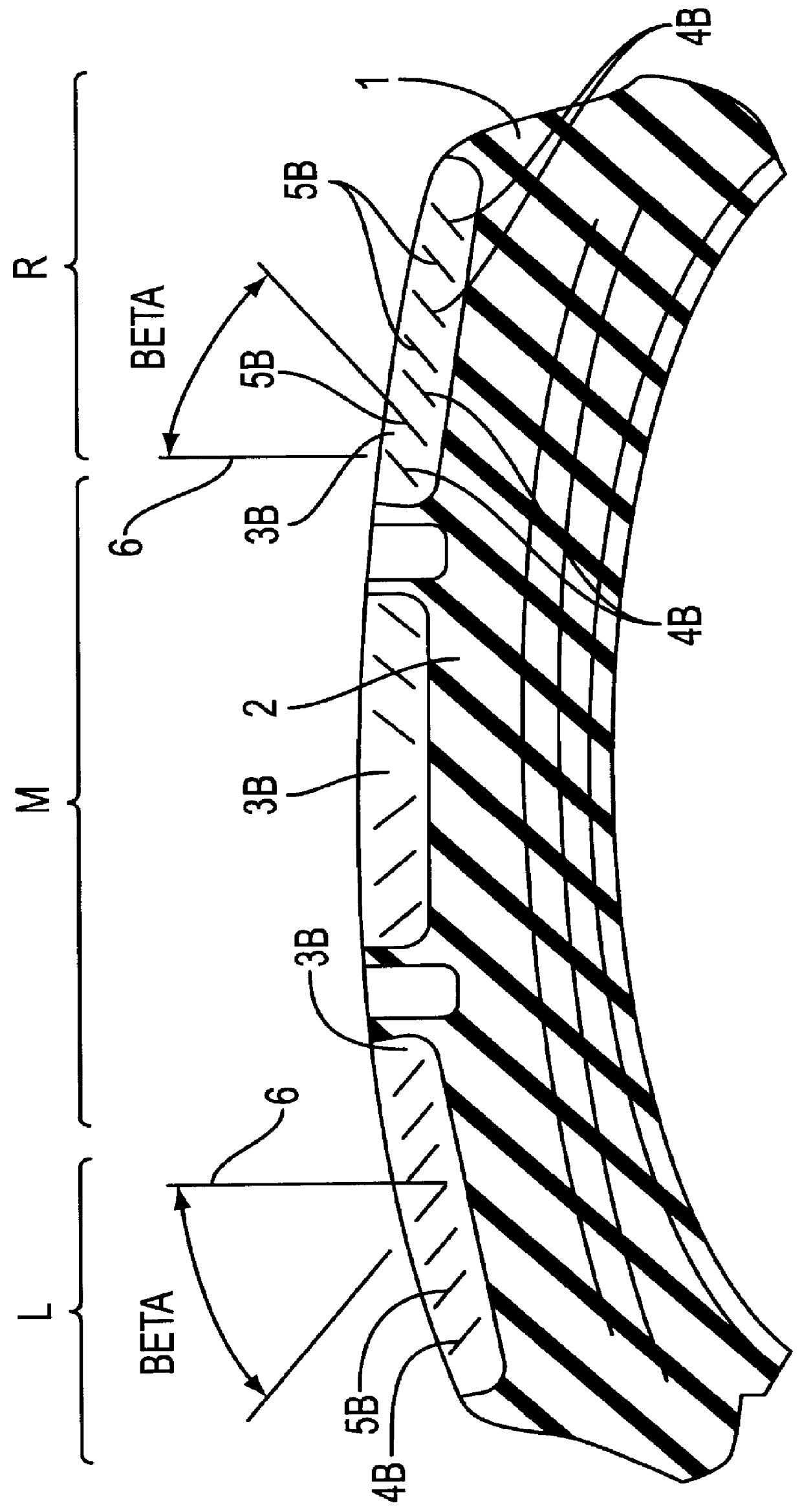
FIG. 1 illustrates a perspective view of a tire 1 including a tread 2 having sipes 3a and 3b running substantially in an axial direction across their entire axial extent when viewed from the top, i.e., perpendicular to the tread 2. A thick dot-dashed, and substantially V-shaped line, forms a section line II--II along sipes 3a (shown in sectioned view as FIG. 2) an...


PUM

PropertyMeasurementUnit
angleaaaaaaaaaa
angleaaaaaaaaaa
angleaaaaaaaaaa

Abstract

Vehicle tire and a metal sheet mold plate for forming the vehicle tire having at least one axial end section includes a tread that includes sipes running substantially axially in at least one of the axial end sections when viewed from the top (i.e., perpendicular to the tread surface). The sipes are corrugated to form corrugated ridges and valleys that are substantially straight lines diagonally inclined in an oblique plane parallel to the substantially axially running sipes. The substantially axially running sipes may include a first set of sipes and a second set of sipes. The corrugated ridges and valleys of the first set of sipes are oriented, with regard to a radially outward direction, to extend axially inwardly toward (i.e., toward a axial center of the tire). Conversely, the corrugated ridges and valleys of the second set of sipes are oriented, with regard to the radially outward direction, to extend axially outwardly (i.e., away from the axial center of the tire). At least one joint track is also provided that includes the corrugated sipes of the first and second sets of sipes.

Description

The present application claims priority under 35 U.S.C. .sctn. 119 of German Patent Application No. 196 50 702.2 filed Dec. 6, 1996, the disclosure of which is expressly incorporated by reference herein in its entirety.1. Field of the InventionThe present invention relates to a vehicle tire including a tread having a plurality of axial end sections and sipes (or slots) running substantially in an axial direction in at least one of the axial end sections when viewed from the top (i.e., perpendicular to the tread surface). As used herein, the term "sipe" refers to a void in the tread which closes up when in the footprint of the tire. The sipes are corrugated with corrugated ridges (or crests or peaks) and valleys such that the corrugated ridges and valleys are substantially straight lines and diagonally inclined in an oblique plane substantially parallel to a longitudinal extent of the sipe.2. Discussion of Background InformationTires similar in general to the type described above are...

Claims


Application Information

Patent Timeline
Patent Type & Authority Patents(United States)
IPC IPC(8): B60C11/13B60C11/12B60C11/04
CPCB60C11/12B60C11/13B60C11/1218B60C11/124B29D2030/0613B60C2011/1213B60C2011/1254Y10S152/03
Inventor DIENSTHUBER, FRANZHAIGERER, CHRISTIANMUNDL, REINHARDRODEWALD, HELMUT
Owner CONTINENTAL AG
Why Eureka
Try Eureka