Matrix-type electrical connector

Inactive Publication Date: 2000-02-22
HON HAI PRECISION IND CO LTD
View PDF8 Cites 95 Cited by
  • Summary
  • Abstract
  • Description
  • Claims
  • Application Information

AI Technical Summary

Benefits of technology

An objective of the present invention is to provide a matrix-type electrical connector for horizontally and electrical

Problems solved by technology

Since the conventional board-to-board connector requires soldering of each connector portion onto a corresponding printed circuit board before the portions are mated together, manufacture and assembly thereof becomes laborious as well as time and cost inefficient.
Furthermore, such a mated connector

Method used


Image

  • Matrix-type electrical connector
  • Matrix-type electrical connector
  • Matrix-type electrical connector

Examples


Embodiment Construction

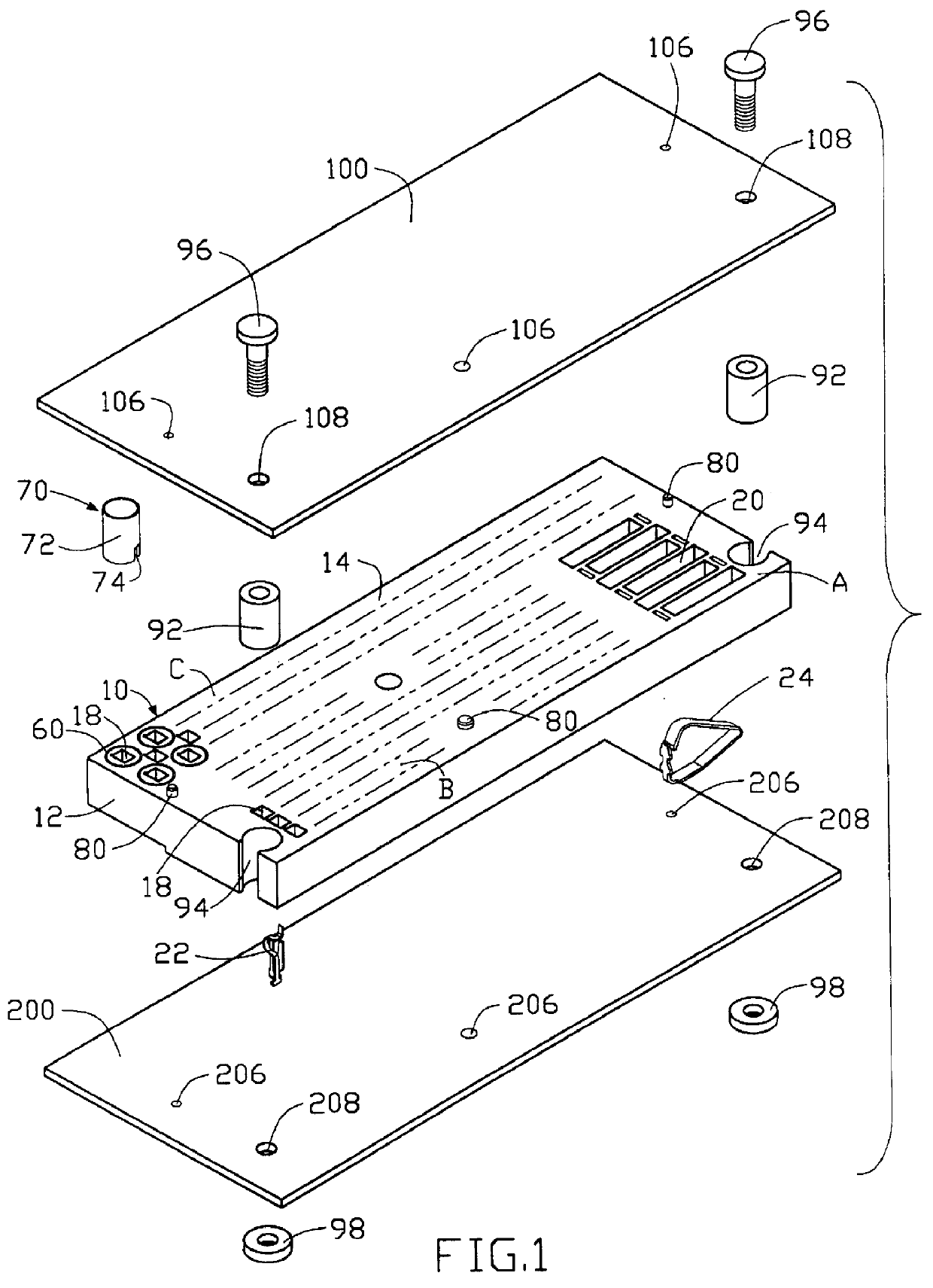
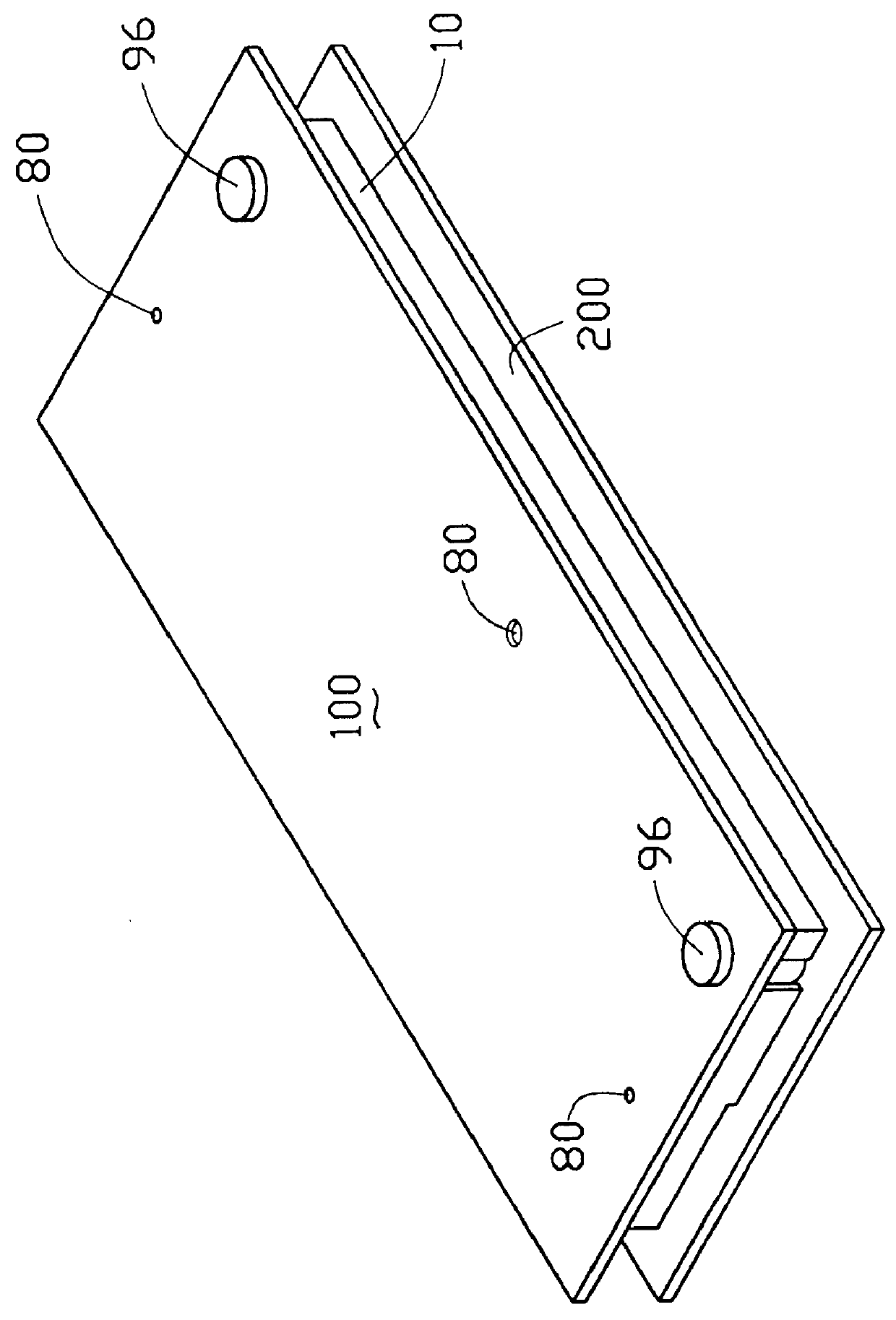
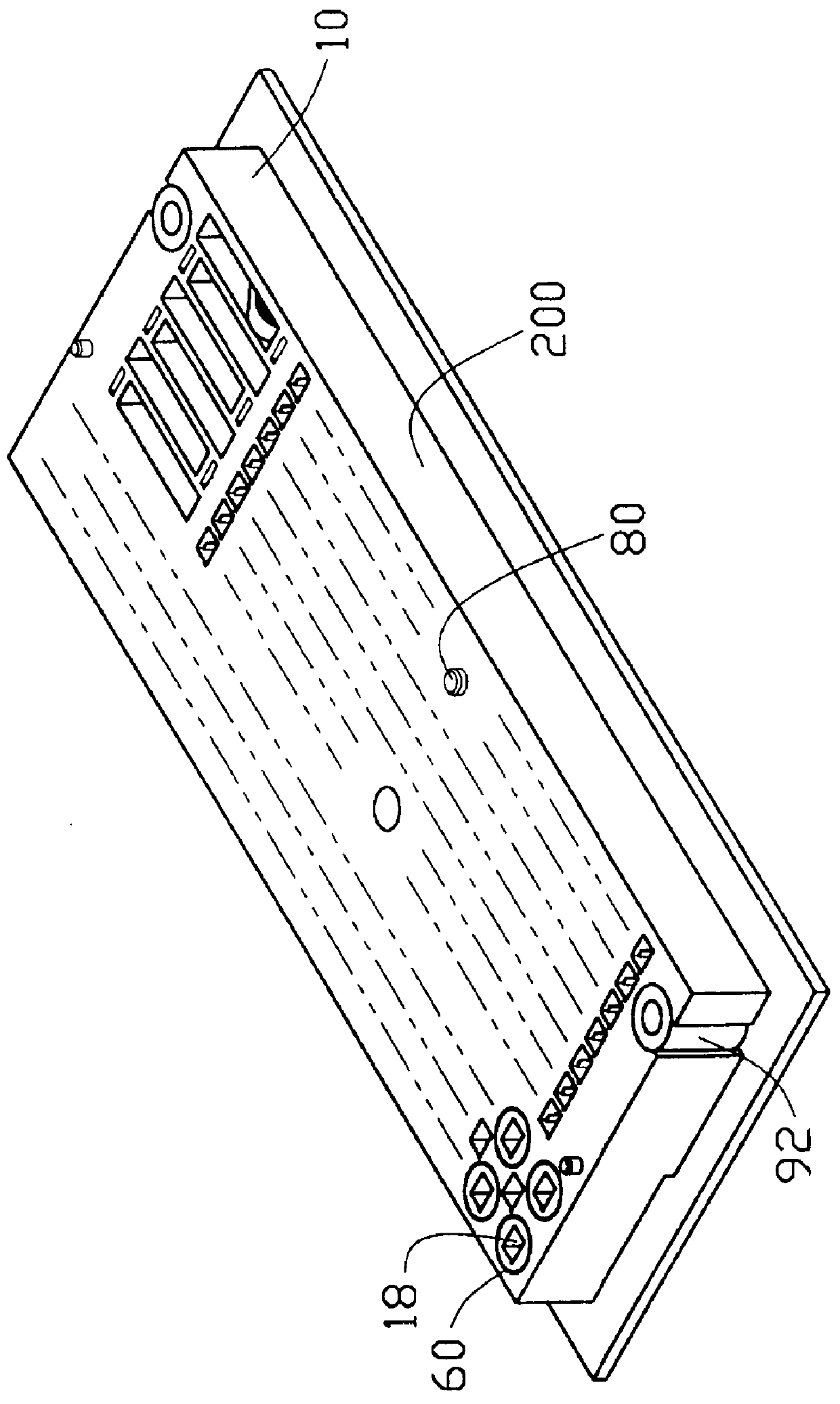
Referring to FIGS. 1-7, an electrical connector 10 for horizontally and electrically engaging a daughter board 100 with a mother board 200 in accordance with the present invention includes an insulative housing 12 having a top surface 14 and a bottom surface 16 and defining a plurality of first passageways 18 and second passageways 20 therethrough for receiving a corresponding plurality of signal contacts 22 and power contacts 24 therein, respectively. An upper engagement portion 26 of each of the power contacts 24 projects beyond the top surface 14 of the connector 10 for respectively engaging with a flat contact pad 102 formed on a bottom surface 104 of the daughter board 100, and a lower engagement portion 28 of each of the power contacts 24 projects beyond the bottom surface 16 of the connector 10 for respectively engaging with a flat contact pad 202 formed on a top surface 204 of the mother board 200.

The signal contacts 22 are C-shaped resilient contacts used for transmitting h...


PUM


Abstract

A matrix-type board-to-board electrical connector for horizontally and electrically engaging a daughter board with a mother board includes an insulative housing having a top surface and a bottom surface and defining a plurality of first and second passageways therethrough. Each first passageway receives a C-shaped resilient signal contact therein for transmitting high or low frequency signals. Each second passageway receives a substantially triangular shaped resilient power contact for carrying a large power current. The first passageways receiving the contacts which transmit high frequency signals either have a circular recess defined therearound for receiving a corresponding cylindrical shielding shell or are located between shielded first passageways thereby providing all of the contacts which transmit high frequency signals with shielding properties. The passageways are defined in the housing of the connector so that the contacts serving the same function are disposed in the same general area of the connector.

Description

BACKGROUND OF THE INVENTION1. Field of The InventionThe present invention relates to an electrical connector, and more particularly to a board-to-board matrix-type electrical connector for transmitting both low and high frequency signals as well as large power currents between a mother board and a corresponding daughter board.2. The Prior ArtThe expansion of a computer's memory and capability is often achieved through the addition of expansion cards (also referred to as daughter boards) electrically connected to a mother board of the computer. The daughter board can be connected to the mother board by means of a vertical card connector which has one surface mounted to the mother board and receives an edge of the daughter board in a slot defined in another surface thereof so that the daughter board is positioned perpendicular to the mother board when electrically engaged therewith. Alternatively, a horizontal card connector can be used to parallel the two printed circuit boards there...

Claims


Application Information

Patent Timeline
IPC IPC(8): H01R13/24H01R13/22H01R12/16H01R12/00H01R9/22H01R9/28H01R12/50H01R12/52
CPCH01R9/096H01R9/28H01R13/2414H01R23/688H01R12/52H01R13/6585
Inventor MCHUGH, ROBERT G.WALKUP, WILLIAM B.LAI, SPENCER
Owner HON HAI PRECISION IND CO LTD
Why Eureka
Try Eureka