Decryption and encryption transmitter/receiver with self-test, learn and rolling code

a transmitter/receiver and encryption technology, applied in the field of decryption and encryption transmitter/receiver with self-testing, learning and rolling code, can solve the problems of transmitter and receiver falling out of sequence with each other, and the retransmission of the same code will not allow the activation of the receiver

Inactive Publication Date: 2000-02-22
TEXAS INSTR INC
View PDF1 Cites 49 Cited by
  • Summary
  • Abstract
  • Description
  • Claims
  • Application Information

AI Technical Summary

Benefits of technology

A pulse width modulated serial data stream is advantageously decoded using a microcontroller, a counter and an external clock signal. Edge detection circuitry detects the rising and the falling edge of the incoming data pulse. An external clock signal clocks a counter to determine how many clock signals the incoming pulse corresponds to. The microcontroller polls the counter on the rising edge and the falling edge and is free to perform other task otherwise without the necessity of using interrupts.

Problems solved by technology

This would normally cause the transmitter and receiver to fall out of sequence with each other.
Since the receiver only activates on the next expected code from the rolling code sequence, interception and subsequent retransmission of the same code will not allow activation of the receiver.

Method used


Image

  • Decryption and encryption transmitter/receiver with self-test, learn and rolling code
  • Decryption and encryption transmitter/receiver with self-test, learn and rolling code
  • Decryption and encryption transmitter/receiver with self-test, learn and rolling code

Examples


first embodiment

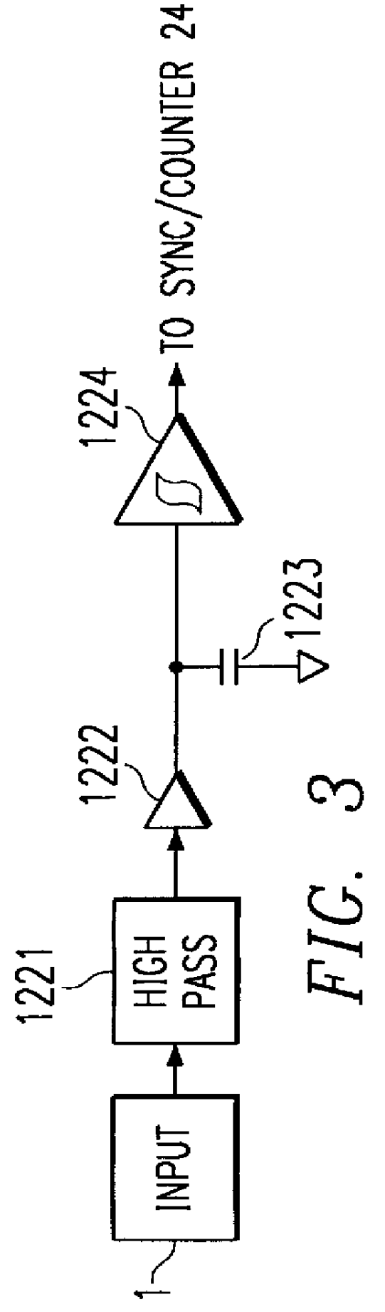
FIG. 3a is a high pass filter 1221 providing AC coupling. Compared with prior art FIGS. 14 and 15, one can verify that the traditional method corresponds to a DC-coupled system. If the comparator is modeled as a linear, high-gain amplifier (with gain A) and it is assumed that the low-pass filter is a first-order system, a simple formula can be written for the comparator output, Y, as a function of the input signal, X:

Y=A(X-X / (1+jf))=AX(1-1 / (1+jf))

Y=AX(jf / (1+jf))

Where f is the first-order pole of the low-pass filter and j is the imaginary unit. Inspection of the second formula reveals a high-pass filter characteristic. This means that the traditional circuit of prior art FIGS. 14 and 15 can be replaced by a high-pass filter configuration as shown in FIG. 3a, without functionality change. This high-pass filter approach has the following advantages:

1. It is AC-coupled, i.e. the DC level (operating point) of the incoming signal is irrelevant, because the signal is passed through a capac...

second embodiment

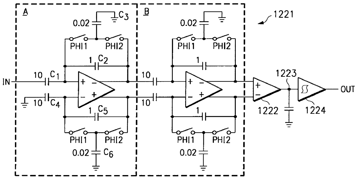
FIG. 3b shows high pass filter 1221 of FIG. 3 having switched-capacitor stages illustrating a practical implementation of an AC-coupled gain stage. The amplifier is assumed to have very large ("infinite") gain. The closed-loop high-frequency gain is set by the ratio of C1 and C2. The DC gain is 0. The time constant (inverse of cut-off frequency) is set by the product of R and C2.

While providing a further improvement, the realization of FIG. 3b may be impractical for implementation within an integrated circuit, because of the very long time constants that are typically needed (millisecond range). In practical systems, the bit-rate is limited to a few kHz, and the time constant must typically be longer than one bit time, as shown above. Such long time constants cannot economically be realized with on-chip resistors and capacitors. Implementation with external capacitors and / or resistors is feasible, but puts more burden (and cost) on the final user.

third embodiment

However, as illustrated in FIG. 3c, the resistor can be replaced by an equivalent switched-capacitor network, where according to the well-known formula:

Req=1 / (C3 fs)

Where fs is the switching frequency and PHI1 and PHI2 are non-overlapping clocks as explained with reference to FIGS. 4 and 5a.

Therefore, the cut-off frequency, fc for the high-pass filter is:

fc=(C3 / C2)fs

The switched-capacitor approach works well as long as the switching frequency (which is normally also the sampling frequency for the incoming signal) is faster than the bit rate. The high pass filter 1221 implementation of FIG. 3c has the following advantages:

1. Long time constants can be realized on-chip.

2. The system is still AC-coupled and self-biasing.

3. The cut-off frequency is set by a ratio of capacitors, which can be matched very well on an integrated circuit.

4. When the sampling rate, fs, is changed (normally because of different expected bit-rate), the cut-off frequency, fc, changes proportionally. This simplif...


PUM


Abstract

A computer implemented method transmits and receives an information signal. A common start position is established for the receive mode where the information signal is received and a transmit mode where the information signal is transmitted. Either the receive mode to receive the information signal or the transmit mode to transmit the information signal is entered subsequent to establishing the common position. The start position is returned to after the receive mode the transmit the learn mode and the self-test mode has been entered.

Description

This invention is in the field of data communications and more particularly relates to decoding a pulse width modulated serial data stream.BACKGROUND OF INVENTIONRemote control or remote access systems use a transmitter and a receiver. An exemplary example is a garage door opener system where a transmitter is contained in a remote control unit and a receiver is connected to a garage door motor. The transmitter and receiver typically include different integrated circuits. When activated, the transmitter sends a serial data stream to the receiver by encoding the data and modulating it onto a radio frequency of infrared carrier.Data encoding (on the transmitter side) into a pulse width modulated format is usually straight-forward. However, decoding (on the receiver side) can be a more complicated operation. Typically, the demodulated incoming signal must be analyzed by comparing the relative width of the incoming pulses, in order to determine which ones represent a logic 1 and which on...

Claims


Application Information

Patent Timeline
Patent Type & Authority Patents(United States)
IPC IPC(8): H04L9/12
CPCH04L9/12H04L9/065H04L9/3226H04L2209/26
Inventor SOENEN, ERIC G.DYCUS, ANGELA C.
Owner TEXAS INSTR INC
Why Eureka
Try Eureka