Integrated approach lighting system and method of use thereof

a technology of integrated lighting and approach lighting, which is applied in the direction of landing aids, waveguides, instruments, etc., can solve the problems of difficult maintenance and repair during operation, large, heavy, and inefficient existing visual landing aid systems

Inactive Publication Date: 2000-02-22
LUMINIT
View PDF10 Cites 31 Cited by
  • Summary
  • Abstract
  • Description
  • Claims
  • Application Information

AI Technical Summary

Problems solved by technology

A previously recognized problem has been that existing visual landing aids systems are relatively inefficient, large, heavy, expensive to install and difficult to maintain and repair during operation.
A previously recognized problem with these systems has been that the spatial separation of the locations of the two systems causes a critical drawback.
Heretofore, there has been no solution to this problem.
However, merely integrating these two systems electrically is not sufficient because the information provided by these two systems in their current form cannot be combined without maintaining spatial separation of the lights themselves.
While conventional optics can be used to shape the light at the distal end of the optical fiber, problems of light loss and overly complicated lens designs have arisen.
Heretofore, remote source lighting applications have been limited to areas where the combination of efficiency and precision are not required, ruling out the use of remote source light for airport approach lighting.

Method used


Image

  • Integrated approach lighting system and method of use thereof
  • Integrated approach lighting system and method of use thereof
  • Integrated approach lighting system and method of use thereof

Examples


Embodiment Construction

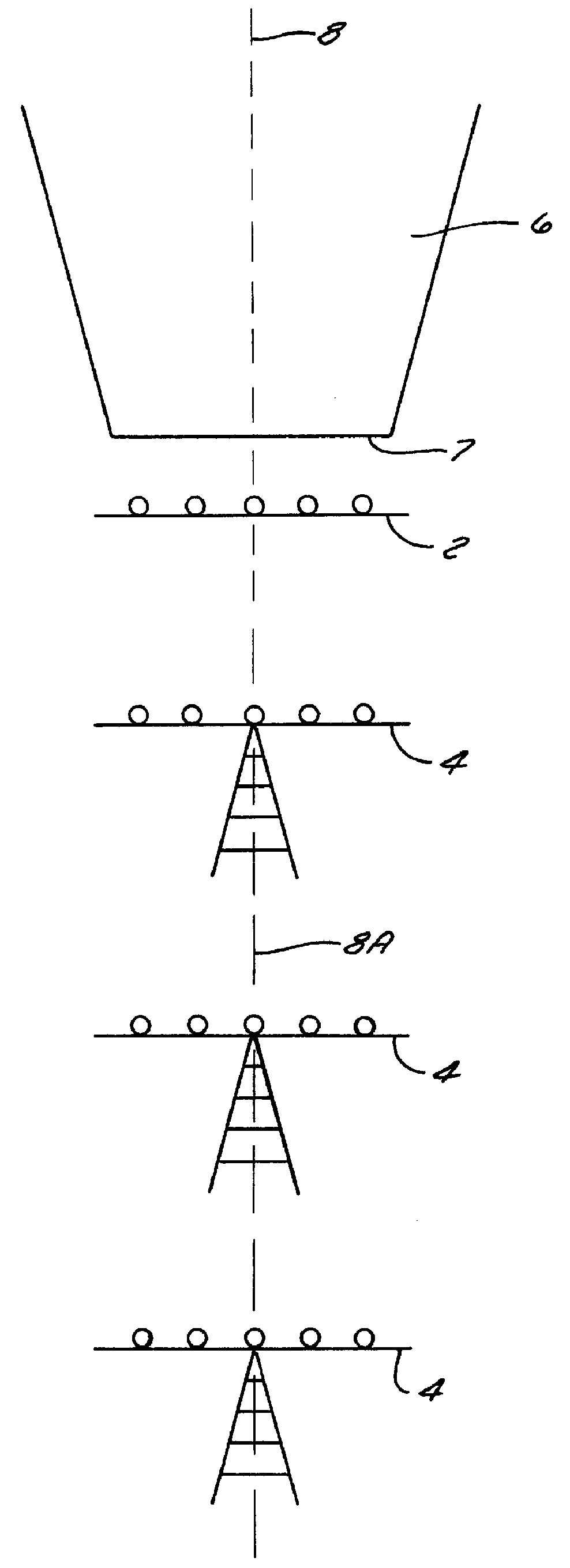
Referring now to FIG. 1, the integrated approach lighting system may preferably comprise a threshold lighting bar 2 and series of lighting towers 4 spaced along an approach path to a runway 6 having a threshold 7, centerline 8, and extended centerline 8A. Threshold lighting 2 may be located at or near the threshold 7 of runway 6 on the ground level and therefore may be termed a threshold lighting bar. Lighting towers 4 are spaced at intervals leading up to the threshold 7 and may be termed approach lighting towers.

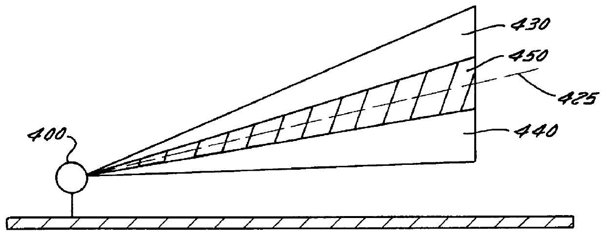
Referring now to FIG. 2, an approach lighting tower 10 in accordance with the present invention is depicted. Referring to approach lighting tower 10, an illuminator 20 is located within the base 30 of tower 10. Light from illuminator 20 travels upward through tower 10 via optical fibers 40. The distal ends of optical fibers 40 are connected to luminaires 50. Luminaires 50 are mechanically connected to light bar 60. Five luminaires are depicted, although light bar 60 can be...


PUM


Abstract

Systems and methods for an integrated approach lighting system are described. An integrated approach lighting system includes a threshold bar and a plurality of lighting towers. The systems and methods provide advantages in that pilots are given a precise three dimensional visual reference to the aircraft's position relative to the runway's centerline, threshold crossing and height above the airfield. This provides the pilot with a higher concentration of visual information to insure faster decision making and an easier, more accurate and safe approach to landing.

Description

1. Field of the InventionThe present invention relates generally to the field of aircraft approach landing systems. More particularly, the present invention relates to visual aircraft approach landing systems. Specifically, a preferred embodiment of the present invention relates to an approach landing system that combines lateral and vertical aircraft position indicating functions that were previously performed by multiple discrete systems. The present invention thus relates to an approach lighting system of the type that can be termed integrated.2. Discussion of the Related ArtHistorically, an important factor in air traffic control is the interaction of humans with engineering systems. Particularly important are decision-making aids to assist pilots before and during landings.Although the rapid advances in communication and computer technology have made the automation of many aircraft crew functions possible, the final portion of an airplane's flight is still based, at least in pa...

Claims


Application Information

Patent Timeline
Patent Type & Authority Patents(United States)
IPC IPC(8): B64F1/20B64F1/00F21V8/00G02B6/24G02B6/26G02B5/02G02B6/28G02B6/00F21S2/00G02B5/20G02B5/32G02B17/00
CPCB64F1/20G02B5/0252G02B5/0278G02B6/0001G02B6/241G02B6/262G02B6/2804G02B6/02033Y10S385/901
Inventor RIZKIN, ALEXANDER
Owner LUMINIT
Why Eureka
Try Eureka