Method and arrangement for radio communication

Inactive Publication Date: 2000-02-22
TELEFON AB LM ERICSSON (PUBL)
View PDF10 Cites 483 Cited by
  • Summary
  • Abstract
  • Description
  • Claims
  • Application Information

AI Technical Summary

Benefits of technology

Another advantage of the present invention is the creation of a method and arrangement for radio communication synchronization which will enable synchronization of a multiple of communication links without causing unacceptable interruptions in interruption sensitive information.
The invention will herein be further explained by means of embodiments with reference to the accom

Problems solved by technology

Transceivers can communicate with each other on a point-to-point or point-to-multipoint basis but have very little knowledge or no knowledge whatsoever of the communications between other transceiver arrangements.
As a result, there is a contention problem; without synchronization, links will mutually interfere if their burst transmission overlaps in time and collisions occur.
For applications in which the links can transfer data and/or speech, packet radio techniques and ALOHA protocols are not attractive.
Retransmissions are impossible since it would give an accumulated delay at the receiver, which means that the error rate on the speech link must remain acceptably low.
Therefore, the number of users that can use the common air interface is rather limited.
Even then, problems may arise if the burst repetition rates of two users drift towards each other, giving continuous collisions during a certain period until the bursts have drifted from each other again.
Without synchronizati

Method used


Image

  • Method and arrangement for radio communication
  • Method and arrangement for radio communication
  • Method and arrangement for radio communication

Examples


Embodiment Construction

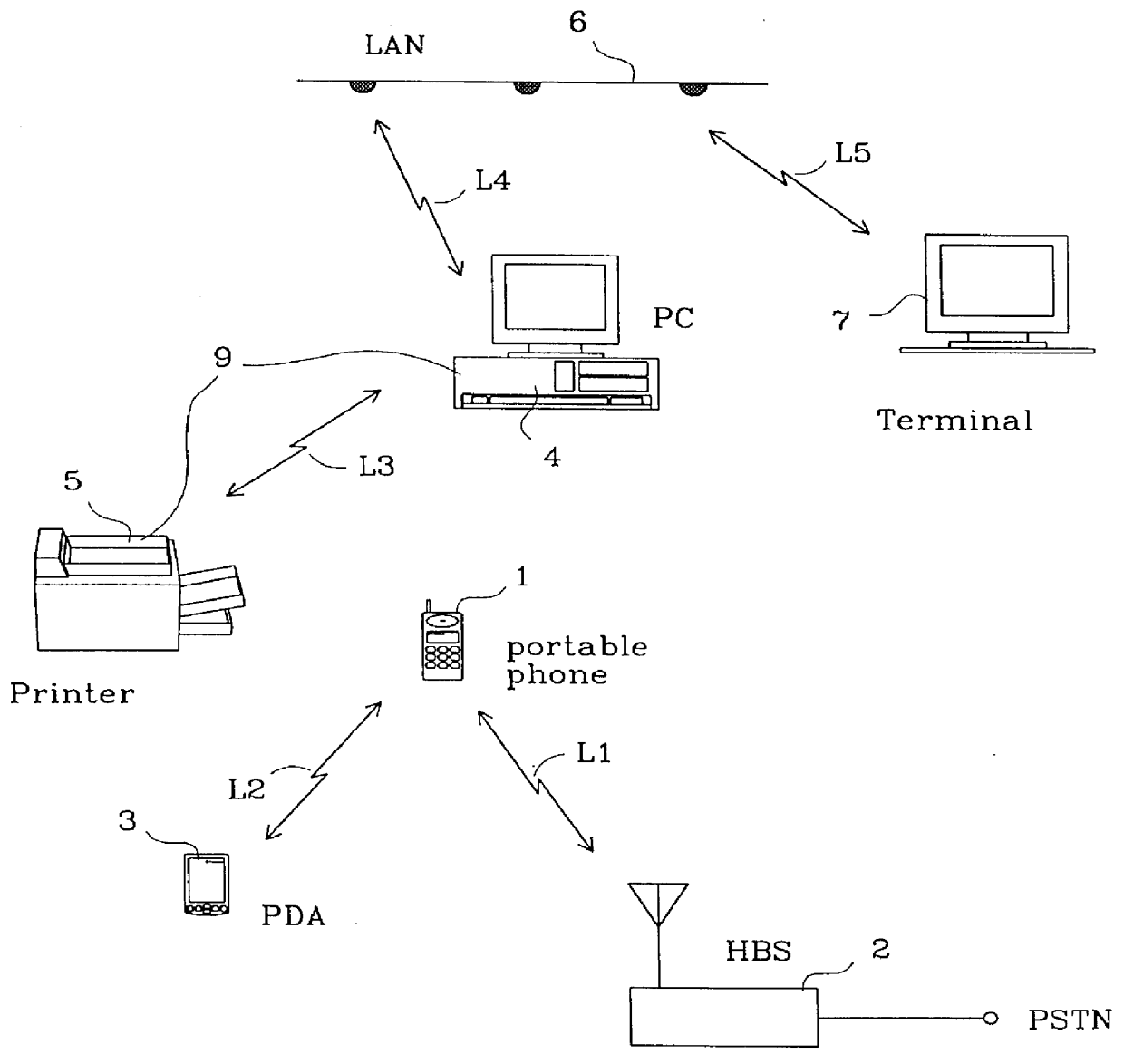
An environment in which the current invention is typically used, is shown in FIG. 1. A number of transceiver arrangements communicating over short-range links L1, . . . , L5 with different characteristics without external synchronization or control share a limited space and a common air interface. Such a cluster of transceivers can be regarded to form an ad-hoc network.

A portable phone 1 is alternately communicating with a home base station (HBS) 2, which is connected to a public telephone network over a PSTN (Public Switched Telephone Network) connection, and to a PDA (Personal Digital Assistant) 3. The communication takes place on two point-to-point links L1 and L2 transferring speech and data on an, in this example, unlicensed band. Sharing the same air interface, there is another transceiver arrangement 9, consisting of a Personal Computer (PC) 4 and a printer 5. The PC has further an analogous wireless connection to a Local Area Network (LAN) 6. On the same air interface the LA...


PUM


Abstract

The present invention relates to a method and arrangement in an ad-hoc network for synchronizing a multiple of radio transceiver arrangements with different characteristics that make use of a common air interface. Each transceiver arrangement comprises at least two transceivers which mutually communicate via a radio transmission link. All transceivers synchronize to a common synchronization signal comprising two staggered beacon pulse series signals (TX1, TX2) which have the same repetition rate. The transceivers synchronize their internal timers which control the signal transmission from the transceivers, to the strongest one of the two beacon pulse series signals (TX1, TX2) by listening during one of the corresponding sets of time windows (RX1, RX2). Between the reception of two beacon pulses, each transceiver transmits beacon pulses itself, thus contributing to the generation of the other beacon pulse series signal, on which other transceivers can lock.

Description

The present invention relates to a method and an arrangement for synchronization of radio transceivers that make use of a common air interface. In addition, a method for obtaining orthogonal traffic channels is presented.DESCRIPTION OF PRIOR ART AND BACKGROUND OF THE INVENTIONMany wireless systems today apply burst transmission; short, repetitive bursts are used to carry the information from transmitter to receiver. An advantage of burst transmission is that the transmit and receive circuitry only has to operate during the presence of the burst. In between the bursts the transceiver can be put in standby mode, thus saving power. This is in contrast to continuous wave (CW) modulation like FM or spread-spectrum transmission where the transceiver has to operate continuously. Burst transmission is therefore attractive in battery driven, portable devices where power consumption is of crucial importance.Current cellular systems like GSM (Global System for Mobile Communication) and D-AMPS ...

Claims


Application Information

Patent Timeline
IPC IPC(8): H04B7/26
CPCH04B7/2687H04B7/2696H04B7/269
Inventor HAARTSEN, JACOBUS
Owner TELEFON AB LM ERICSSON (PUBL)
Why Eureka
Try Eureka