Apparatus for regenerating desiccants in a closed cycle

a technology of desiccant and closed cycle, which is applied in the direction of domestic cooling apparatus, heating types, separation processes, etc., can solve the problems of water vapor and heat being rejected and lost from the system, and achieve the effects of low manufacturing cost, convenient and efficient manufacturing and marketing, and durable and reliable construction

Inactive Publication Date: 2000-02-29
MORATALLA JOSE M
View PDF7 Cites 122 Cited by
  • Summary
  • Abstract
  • Description
  • Claims
  • Application Information

AI Technical Summary

Benefits of technology

It is another object of the present invention to provide a new and improved method and apparatus for regenerating desiccants in a closed cycle which may be easily and efficiently manufactured and marketed.
It is further object of the present invention to provide a new and improved method and apparatus for regenerating desiccants in a closed cycle which is of durable and reliable constructions.
An even further object of the present invention is to provide a new and improved method and apparatus for regenerating desiccants in a closed cycle which is susceptible of a low cost of manufacture with regard to both materials and labor, and which accordingly is then susceptible of low prices of sale to the consuming public, thereby making such method and apparatus for regenerating desiccants in a closed cycle economically available to the buying public.

Problems solved by technology

Again, water vapor and heat is rejected and lost from the system.

Method used


Image

  • Apparatus for regenerating desiccants in a closed cycle
  • Apparatus for regenerating desiccants in a closed cycle
  • Apparatus for regenerating desiccants in a closed cycle

Examples


Embodiment Construction

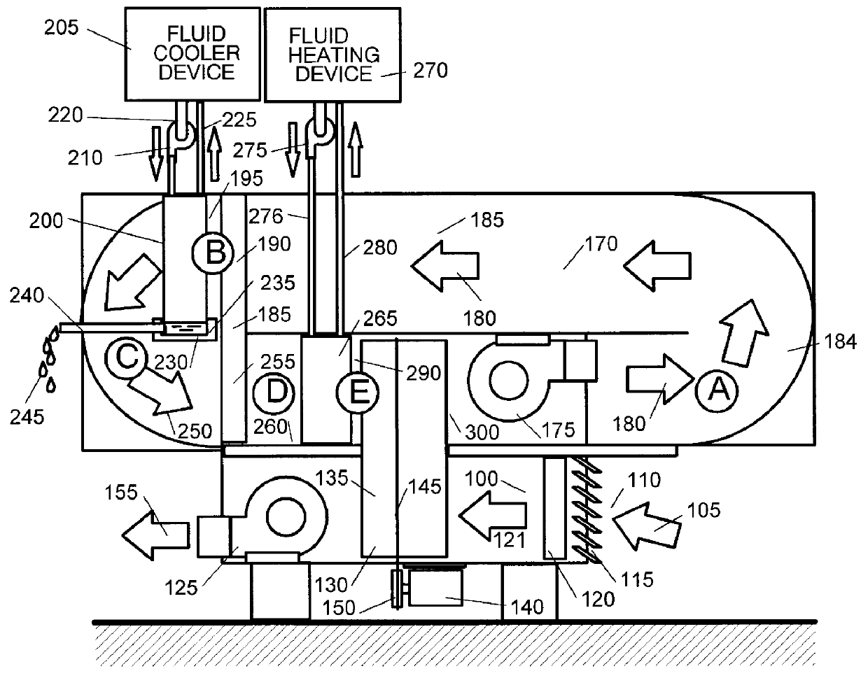
With reference now to the drawings of FIG. 3, the first path 100 is integrated for an air or gas intake 105 comprising of an undesired content of humidity, higher than is required, which is drawn through outside air intake 110 and louver 115 and air filter 120 creating a flow of filtered air 121 by means of suction provided by a forced air intake blower 125 which further forces system input air 105 through a desiccant matrix or core 130. This matrix can be shaped in the form of a wheel 135 which is rotating during operation by a motorized driving mechanism 140, the motion being transmitted by a belt or chain 145. The relationship between the motorized driver 140 and belt or chain 145 is with a pulley or roller 150.

Very dry air 155 after the desiccant matrix is pulled by blower 125 which delivers this air 155 as conditioned or processed air essentially free of moisture.

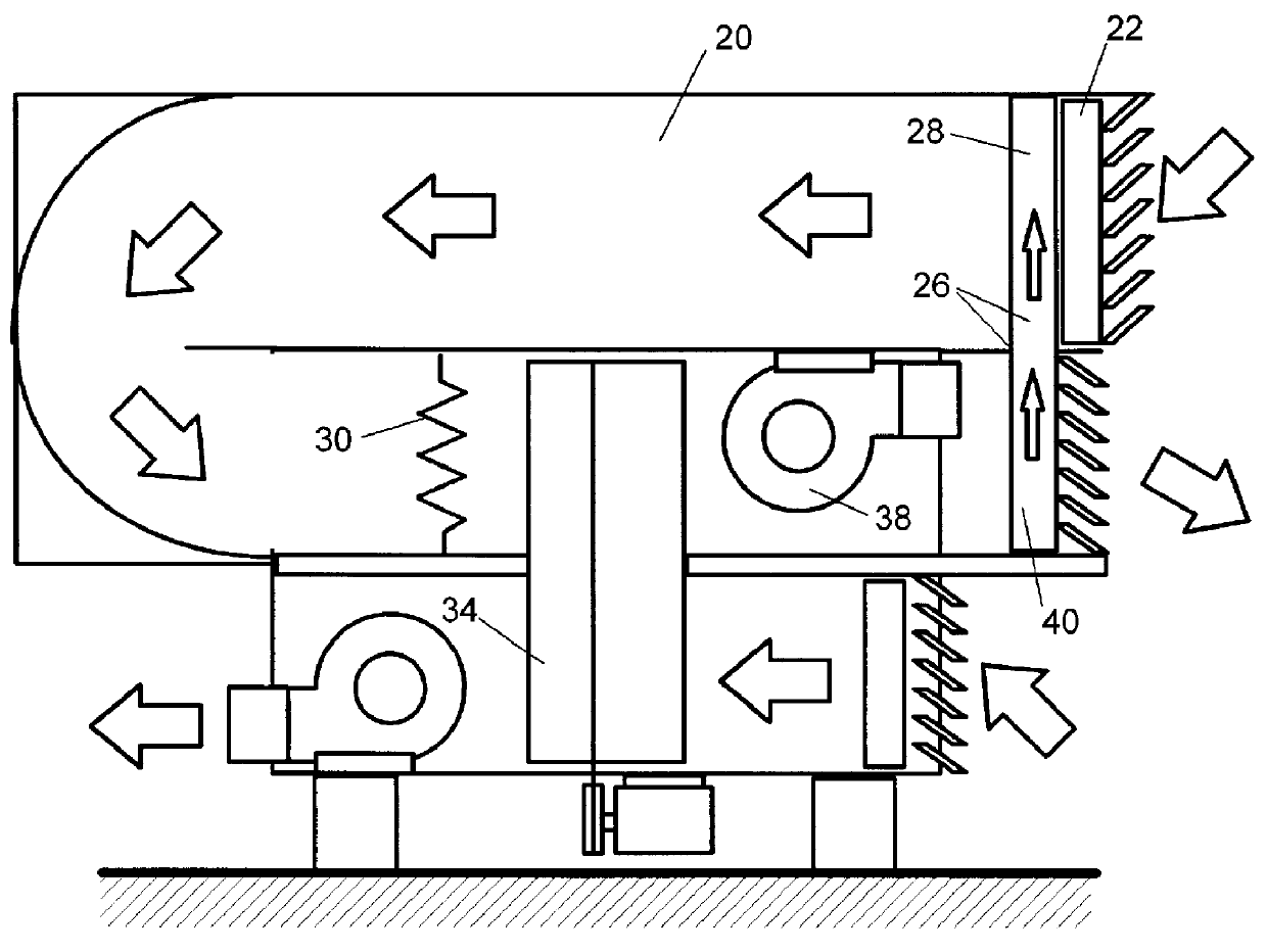
A second path or closed loop regeneration path 170 is integrated and includes a regeneration blower 175 that pushes ...


PUM


Abstract

A method and apparatus for conditioning air through the removal of moisture from air to be conditioned comprising a first path for a first flow of air to be dehumidified, the first path having an input end and an output end with a first blower between the input end and the output end to effect the movement of air from the input end to the output end; a second path for a second flow of air, the second path being independent of the first path and adapted to remove moisture from the second flow of air, the second path being in a closed loop configuration with a second blower for continuously moving the second flow of air around the second path and with a plurality of temperature changing devices sequentially positioned in the second path including an air precooling device, a cooling condenser device for condensing moisture from the second flow of air, a reheating device coupled to the precooling device, and a heating device; and a desiccant wheel with a motor to rotate the wheel in a continuous path of travel through a first zone and a second zone, the first zone being in the first path of travel between the input end and the output end, the second zone being in the second path of travel between the heating device and the precooling device.

Description

1. Field of the InventionThe present invention relates to an improved apparatus for regenerating desiccant in a closed cycle and, more particularly, to providing a second regeneration path totally in a closed loop, a closed cycle desiccant regeneration system wherein an array of heat exchangers recovers a major percentage of the thermal energy that drives the cycle with only condensation constituting energy lost.2. Description of the Prior ArtOpen cycle desiccant systems have been known from the early 1940's. In 1955, Pennington U.S. Pat. No. 2,700,537 was using rotary heat exchangers impregnated with desiccants. Today dual path machines similar to FIG. 1 herein use the Pennington cycle. In 1960, Munters U.S. Pat. No. 2,926,502 improved this cycle. The '502 patent discloses an air conditioning system including the recycling of air, at least three air flow paths, with all embodiments including a recycling of interior space conditioned air path, an open cycle regeneration path and a s...

Claims


Application Information

Patent Timeline
Patent Type & Authority Patents(United States)
IPC IPC(8): B01D53/26F24F3/14F24F5/00F24F3/12
CPCB01D53/265F24F3/1411F24F3/1423F24F5/001F24F2003/144F24F2003/1458F24F2203/1084F24F2203/1012F24F2203/1016F24F2203/1032F24F2203/1056F24F2203/1068F24F2203/1004
Inventor MORATALLA, JOSE M.
Owner MORATALLA JOSE M
Why Eureka
Try Eureka