Process and apparatus for the formation of patterns in a photoresist by continuous laser irradiation, application to the production of microtips emissive cathode electron sources and flat display screens

a technology of emissive cathode electron source and photoresist, which is applied in the direction of electrical apparatus, electric discharge lamps, instruments, etc., can solve the problems of difficult to produce a mask in excess of 14 inches diagonal using conventional microelectronics methods, and the process of producing this pattern of holes rapidly becomes constrictive, etc., to achieve the effect of large-scale electron source production, and the difficulty of using direct projection and other photorepetition

Inactive Publication Date: 2000-02-29
COMMISSARIAT A LENERGIE ATOMIQUE ET AUX ENERGIES ALTERNATIVES
View PDF11 Cites 50 Cited by
  • Summary
  • Abstract
  • Description
  • Claims
  • Application Information

AI Technical Summary

Problems solved by technology

In the case of large electron sources, larger than 14 inches (approximately 35 cm), the process of producing this pattern of holes rapidly become constrictive.
It is difficult to produce this mask in excess of 14 inches diagonal using conventional microelectronics methods.
These two methods (one using direct projection and the other photorepetition) are consequently difficult to apply to the production of large electron sources.
Thus, no information is given on the uniformity defects, which would probably appear as a result of imperfections of the profile of the laser beams.
Moreover, this method significantly restricts the choice of the configuration and distribution of the holes.
They supply a peak power of a few watts, which could satisfy the application considered here, but it is presently impossible in the state of the art to focus the laser beam onto such small surfaces.
Thus, microlasers are unusable for the application considered here.
Thus, these gas laye

Method used


Image

  • Process and apparatus for the formation of patterns in a photoresist by continuous laser irradiation, application to the production of microtips emissive cathode electron sources and flat display screens
  • Process and apparatus for the formation of patterns in a photoresist by continuous laser irradiation, application to the production of microtips emissive cathode electron sources and flat display screens
  • Process and apparatus for the formation of patterns in a photoresist by continuous laser irradiation, application to the production of microtips emissive cathode electron sources and flat display screens

Examples


Embodiment Construction

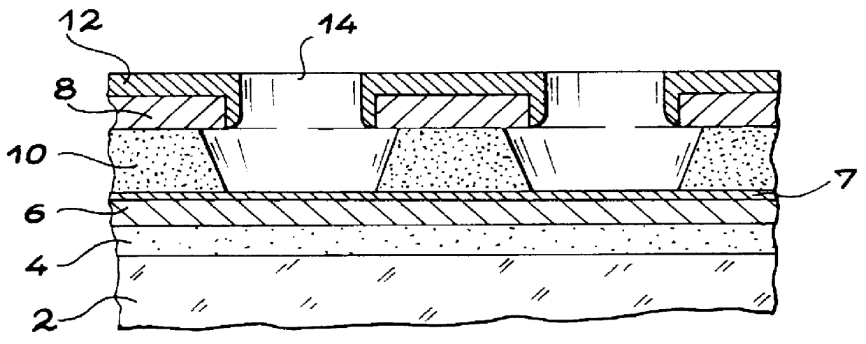
FIG. 4 diagrammatically and partially shows the structure referred to in the description of FIGS. 1 to 3 and which comprises the substrate 2, insulator 4, cathode conductors 6, resistive layer 7, grids 8 and intermediate insulator 10. The aim is to make holes in the grids 8 and the intermediate insulator 10 by means of a process according to the inventions. In order to make these holes, on the surface of the structure 20 in FIG. 4, is deposited a positive photosensitive resin layer or photoresist 22.

The apparatus diagrammatically shown in FIG. 4 and whereof part is shown in greater detail in FIG. 5, makes it possible to perform a process according to the present invention. This apparatus comprises a YAG laser 24 supplying a light beam, a bundle 26 of optical fibres 28 and means 30 for focusing the light beams. These focusing means 30 incorporate a linear array or strip 32 equipped with microlenses 34 respectively associated with the optical fibres 28. One end of each optical fibre 2...


PUM


Abstract

Process and apparatus for the formation of patterns in a photosensitive resin layer or photoresist by continuous laser irradiation, application to the production of microtip emissive cathode electron sources and flat display screens. Formation takes place of non-mutually interfering elementary light beams (41), there is at least one relative translation at constant light power and speed of said beams with respect to the layer in order to irradiate lines thereof, each line receiving a light dose lower than that necessary for the development of the resin, a relative rotation of all the beams with respect to the layer takes place, the translation is recommenced in order to irradiate other lines, each line receiving a light dose complimentary to the preceding dose and the resin is developed.

Description

1. Technical FieldThe present invention relates to a process for the formation of patterns (e.g. holes), in a photosensitive resin layer or photoresist, as well as to an apparatus for performing this process. The invention more particularly applies to the production of microtip emissive cathode electron sources, which are more particularly used in the fabrication of display means by cathodoluminescence excited by field emission. The invention makes it possible to produce microtip flat screens of a larger size than that of the prior art (e.g. exceeding 14 inches and even microtip flat screens with an area close to 1 m.sup.2).2. Prior ArtMicrotip emissive cathode electron sources and their production processes are described in (1) FR-A-2 593 953 (cf. also EP-A-234 989); (2) U.S. Pat. No. 4,857,161 (corresponding to document (1); (3) FR-A-2 663 462 (cf. also EP-A-461 990 and U.S. Pat. No. 5,194,780); (4) FR-A-2 687 839 (cf. also EP-A-558 393 and U.S. patent application Ser. No. 08 / 022,...

Claims


Application Information

Patent Timeline
IPC IPC(8): G03F7/20H01J9/02H01J31/12H01L21/027
CPCG03F7/2022G03F7/2053G03F7/70075G03F7/70383H01J9/025H01J2329/00
Inventor IDA, MICHELRABAROT, MARC
Owner COMMISSARIAT A LENERGIE ATOMIQUE ET AUX ENERGIES ALTERNATIVES
Why Eureka
Try Eureka