Printing roller for channel-free printing

a printing roller and printing technology, applied in the field of printing rollers, can solve the problems that plastic sheets as known in the art are not applicable to use with sleeves

Inactive Publication Date: 2000-03-21
MANROLANAD AG
View PDF19 Cites 33 Cited by
  • Summary
  • Abstract
  • Description
  • Claims
  • Application Information

AI Technical Summary

Problems solved by technology

However, such plastic sheets as known in the art

Method used


Image

  • Printing roller for channel-free printing

Examples


Embodiment Construction

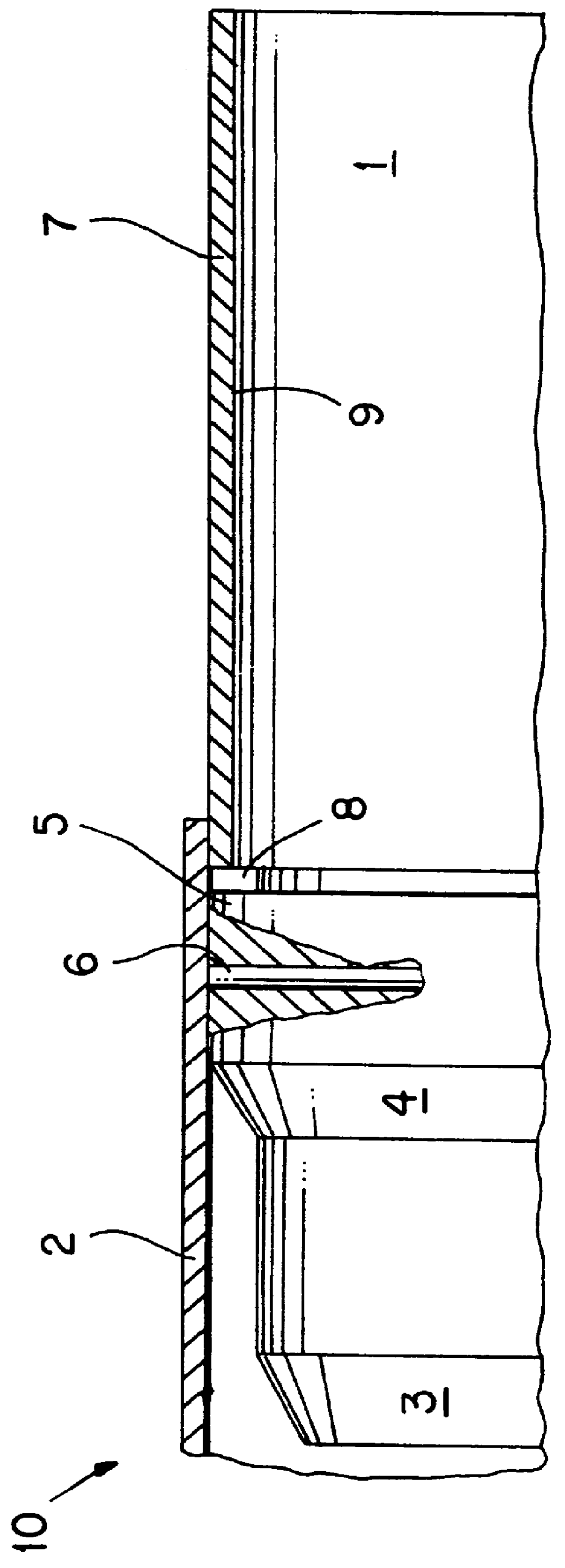
FIG. 1 is a schematic view of a partial longitudinal section of a printing roller 10 with a printing or transfer form 2 partially slid onto its roller core 1.

The roller core 1 is normally constructed as a hollow body having a greater wall thickness than the sleeve-shaped printing or transfer form 2 and is constructed to have cylinder diameter which is larger than the relaxed inner diameter of the printing or transfer form 2.

In order to facilitate the application of the printing or transfer form 2, a cylindrical piece in the form of a pre-centering cone 3 having a smaller diameter than the relaxed inner diameter of the printing or transfer form 2 is provided at one end face of the printing roller 10, and the printing or transfer form 2 can be roughly positioned on the printing roller 10 via this pre-centering cone 3.

When pushed farther onto a conical slip-on cone 4 of the printing roller 10 positioned between the pre-centering cone 3 and the roller core 1, the printing form 2 is expa...


PUM


Abstract

A printing roller for channel-free printing, in particular for a rotary offset printing machine including a roller core 1 on which a sleeve-shaped printing or transfer form 2 can be positioned. The roller includes a thin intermediate layer 7 provided at least partially between the outer surface of the roller core 1 and the inner surface of the sleeve-shaped printing or transfer form 2 for adjusting the printing or transfer form 2 on the printing roller 1, 3, 4, 6 and for securing the printing or transfer form 2 in an improved manner. The printing roller constructed according to the present invention allows a sleeve-shaped printing or transfer form to be adjusted or fitted precisely and in a stationary manner on the printing roller when slid onto the printing roller without limiting the principle on which the sleeve technique for printing is based.

Description

1. Field of the InventionThe present invention relates to printing rollers and, more particularly, to printing rollers on which a sleeve can be precisely aligned.2. Description of the Prior ArtIn modern sleeve technology, that is, in techniques for channel-free printing--specifically with a rubber blanket and printing form--the sleeve-shaped printing form or transfer form is conventionally applied to a printing roller by expanding the printing form or transfer form using compressed air and slipping the printing form onto the printing roller. When the compressed air is removed, the printing form or transfer form contacts the printing roller in a positive engagement based on the principle of a shrinkage fit. The printing form or transfer form can be removed again from the printing roller by once again supplying compressed air. As a rule, such a printing roller is normally manufactured from a metallic work material and preferably has a chrome coating to protect it from corrosion due to...

Claims


Application Information

Patent Timeline
IPC IPC(8): B41F27/00B41F27/10B41F13/08B41F13/10B41F27/06B41F30/00
CPCB41F27/105
Inventor HOFFMANN, EDUARDPREM, WOLFGANG
Owner MANROLANAD AG
Why Eureka
Try Eureka