Air-drying system, in particular for rail vehicles

a technology for rail vehicles and air-drying systems, which is applied in the field of air-drying systems, can solve the problems of excessive air and energy consumption during normal operation

Inactive Publication Date: 2000-03-28
KNORR BREMSE SYST FUR SCHIENENFAHRZEUGE GMBH
View PDF5 Cites 5 Cited by
  • Summary
  • Abstract
  • Description
  • Claims
  • Application Information

AI Technical Summary

Benefits of technology

In comparison to the above mentioned state of the art, according to the invention at least one further regeneration line, which may be switched on and off as necessary, is connected between the two chambers. The two regeneration lines which preferably provided with respective regeneration orifices, preferably together comprise a cross-sectional area that corresponds to the cross-sectional area of the single typical orifice that is used in the conventional system. By providing the further or additional regeneration line, the regeneration can be carried out with the proper regeneration airflow rate as needed, depending on the operating requirements, in contrast to the state of the art. During the operation of only one compressor, the connection via the additional regeneration orifice is interrupted, so that the air consumption is reduced in normal operation. This in turn leads to a considerable energy savings.

Problems solved by technology

This results in an excessive air and energy consumption during normal operation.

Method used


Image

  • Air-drying system, in particular for rail vehicles
  • Air-drying system, in particular for rail vehicles

Examples


Embodiment Construction

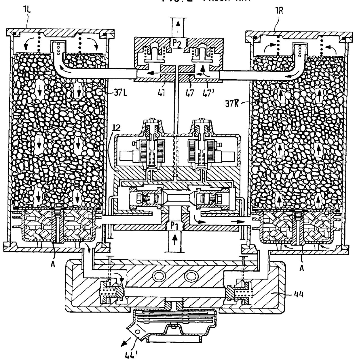
FIG. 2 shows an air-drying system according to the prior art, in an operating position in which a first or right chamber 1R is in a drying phase and the second or left chamber 1L is in the regeneration phase. With regard to the basic function and operation of this air-drying system, reference is made to the device description "B-MA 20.27" published by the company Knorr-Bremse Systeme fur Schienenfahrzeuge GmbH, Munich, Germany. The essential elements in air flow direction sequence include a pressurized air connection P1 of the compressors, a switching value unit 12, a structural group representing the oil separator A, the right chamber 1R with adsorbate 37R, the regeneration unit 47', the left chamber 1L with adsorbate 37L, the other side of the switching valve unit 12 and a de-watering valve 44 with an exhaust outlet 44'. The functional operation of the prior art system is described above under "Background Information".

In comparison to the above prior art, the invention distinguish...


PUM


Abstract

PCT No. PCT / DE97 / 00487 Sec. 371 Date May 11, 1998 Sec. 102(e) Date May 11, 1998 PCT Filed Mar. 11, 1997 PCT Pub. No. WO97 / 42068 PCT Pub. Date Nov. 13, 1997An air-drying system, in particular for the pneumatic braking systems of rail vehicles, including at least two air-drying chambers (1L, 1R) interconnected with one another via first and second regeneration lines (2 and 2'). In a reversibly switchable manner one of the chambers is used for air drying and the respective other chamber is used for regeneration of the air-drying agent (adsorbate) contained in the chambers. The second regeneration line (2') can be switched on and off as necessary to provide two different flow rates of regeneration air.

Description

The invention relates to an air-drying system, in particular for pneumatic brake systems of rail vehicles, which comprises at least two air-drying chambers interconnected with one another via a regeneration line, whereby normally, in a reversibly switchable manner, one of the chambers is used for air drying and the respective other chamber is used for regeneration of the air-drying agent contained in the chambers.BACKGROUND INFORMATIONSuch air-drying systems are known in the state of the art, and are, for example, distributed by the company Knorr-Bremse. FIG. 2 shows such a prior art-drying system. According to FIG. 2, a cold generating adsorption dryer in a two-chambered embodiment is operated in a two-phase manner, i.e. one drying phase and one regeneration phase are carried out in parallel or simultaneously with one another. While the main airstream is dried in one chamber, for example the right chamber 1R, chamber ) the drying agent in the other chamber 1L is regenerated. As the...

Claims


Application Information

Patent Timeline
Patent Type & Authority Patents(United States)
IPC IPC(8): B60T17/00
CPCB60T17/004
Inventor ZOERNER, WILFRIEDFIEBIGER, VIKTOR
Owner KNORR BREMSE SYST FUR SCHIENENFAHRZEUGE GMBH
Why Eureka
Try Eureka