Concrete and tire artificial reef

a technology of concrete and tires, applied in the field of fishing, can solve the problems of concrete weight and the cost of fiberglass and steel, limiting the size of artificial reef devices, and steel is expensive and will deteriorate, and their designs have not been able to meet the regulations

Inactive Publication Date: 2000-03-28
WALTER DAVID M
View PDF7 Cites 15 Cited by
  • Summary
  • Abstract
  • Description
  • Claims
  • Application Information

AI Technical Summary

Problems solved by technology

The weight of concrete and the cost of fiberglass and steel sets limits on the size of an artificial reef device due to weight and cost.
Steel is expensive and will deteriorate in a salt water environment.
These are usually made small, due to material cost and weight, with a small surface area.
That is why, under the present regulations set forth by the National Marine Fisheries and The U.S. Army Corps of Engineers for artificial fishing reef devices using tires, each tire must be imbedded or captured in concrete two times the weight of the tire plus 10%. many tire reef devices have been patented, but their designs have been unable to meet the regulations set forth by the above.
This method produced a very undesirable reef device, because, due to its size and weight, the reef device would sink into the sand, with little remaining as a surface area for marine growth.
Since height and surface area are the two of the most important qualities in an artificial reef device, the use of tires in artificial reefs was not well accepted, due the limitations mentioned in previous reef devices.
Artificial reef structures to date have failed for one reason or another to meet the commercial needs of fisherman.
The unit is not practical for artificial reefs due to cost, deterioration in salt water and small surface area.
It uses no tires and provides no means for preventing sinking into the bottom.
This practice is unlawful in the United States and can not meet the requirements set forth by the U.S. Army Corps of Engineers.
This reef device is designed to float and not rest on the bottom, making it difficult to anchor and survive storms in open water.
This type of structure is also unlawful in the Untied States and can not meet the requirements set forth by the US Army Corps of Engineers for artificial tire reef devices.
This reef device is costly and its weight limits its size.
Its small size to weight foot print will cause it to rapidly sink into the sea bottom.
This will make a good artificial barrier as was his intent, but a poor artificial reef device.
It does not provide a very large surface area for marine growth and its foot print to weight ratio is poor, causing it to sink into the sand.
The manufacture is costly and so is the transport and deployment, due to its unstackability.
The drawbacks to this method are the reef device can stand no taller than the diameter of the tire, a large suface area of the tire is wasted for marine growth, due to it being imbedded in concrete.
Some settling is expected for any reef device and this device will all but disappear into the bottom, due to its short height.
This pratice for an artificial reef device is unlawful in the United States. and if it were legal, would make a poor reef device, due to height and small amount of weight.
It would tend to roll away during storms or rapid current.
The device uses concrete and tires in an ineffecient manner.
The excessive small foot print to weight ratio will cause the device to sink into the sand, rendering the device ineffective as an artificial reef device.
This will cause the reef to sink a few inches into the bottom.

Method used


Image

  • Concrete and tire artificial reef
  • Concrete and tire artificial reef
  • Concrete and tire artificial reef

Examples


Embodiment Construction

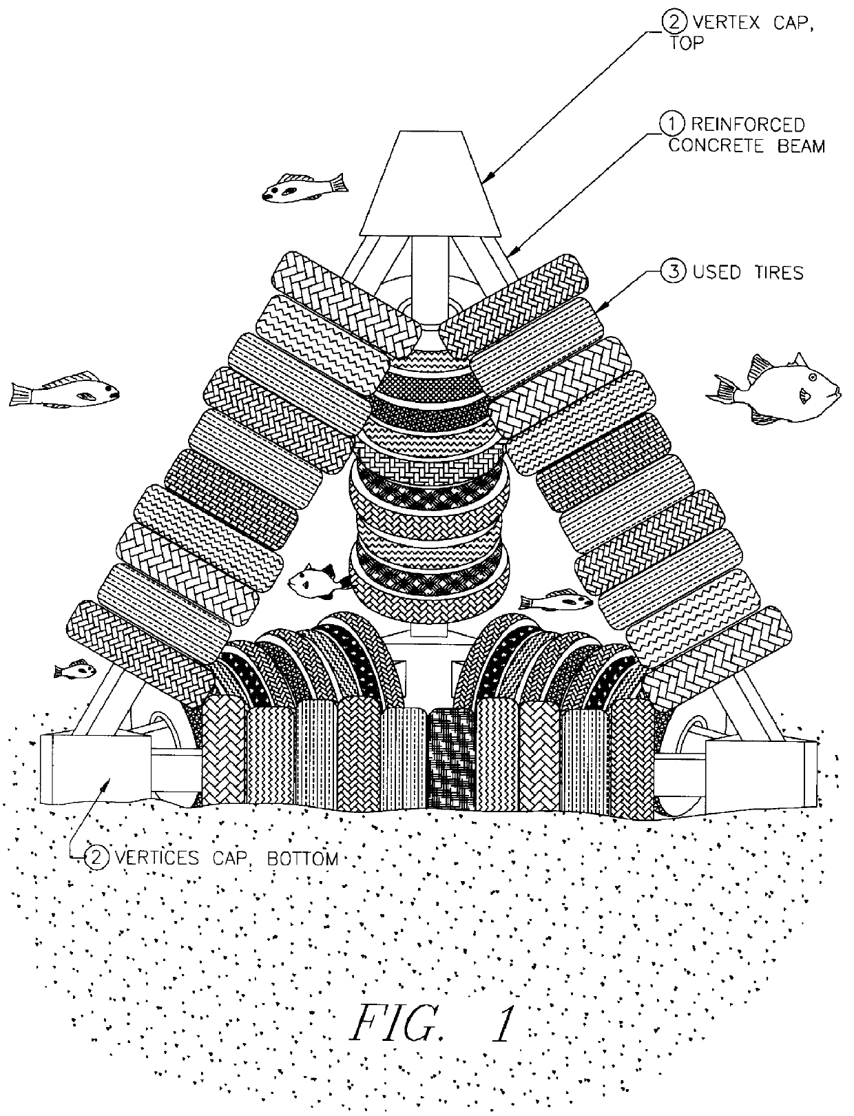
FIG. 1 is a side view of the equilateral tetrahedral frame reef showing the six concrete beams 1 joined together at four joints 2. Each beam 1 is inserted through the center of a number of automotive tires 3. The tires 3 are loose on the beams 1 and free to rotate and move up and down movement along the beam 1, but up and down movement is limited by the joints 2.

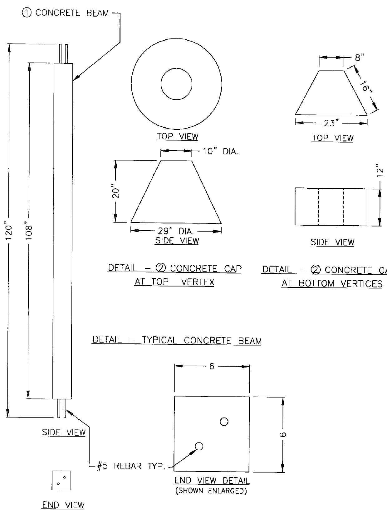
FIG. 2 is a side and end view of one of the six concrete beams 1, with protruding rebar from the ends. Also shown are top and side views of the concrete joints 2 used to cover the rebar joints at the four joints 2.

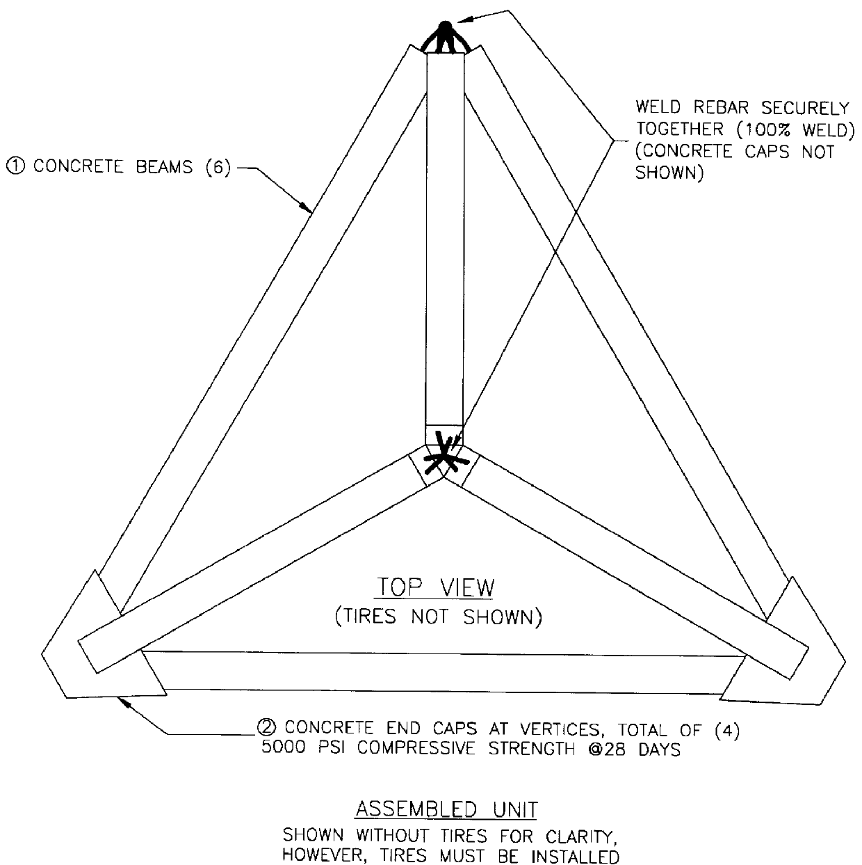
FIG. 3 is a top view of the reef showing how the concrete beams 1 with rebar protruding from the ends are joined and welded pior to the poured concrete joint 2.

FIG. 4 is a top view of a completed reef (without the normally installed tires 3) showing the six beams 2 with the four concrete caps 2.

FIG. 5 shows a side view of the completed reef.

PREFERRED EMBODIMENT--OPERATION

This reef has no moving parts. The design is...


PUM


Abstract

An equilateral tetrahedral frame, comprising six concrete beams inserted through the center of a number of automotive tires. The ends of the concrete beams are fastened together at four points. These four points are covered by a cap of concrete to seal the fastening points. The reef device may be of any size. The design permits ease of transport due to its ability to stack one upon another uniqueness of this reef is in the design. Once the reef is transported to its desired location, it can lowered or dropped to the sea floor.

Description

BACKGROUND1. Field of InventionMachine / MechanicalThis invention relates to fishing, specificity to an apparatus combining recycled automobile tires and a concrete pile tetrahedral frame to form an improved artificial fishing reef.2. Description of Prior ArtMost commercially manufactured artificial reef devices are made of concrete, steel and / or fiberglass or a combination of the three. The weight of concrete and the cost of fiberglass and steel sets limits on the size of an artificial reef device due to weight and cost. Steel is expensive and will deteriorate in a salt water environment. Many artificial reef devices are made exclusively of concrete and some use some type of tire chips. The chips are mixed with the concrete and only serve as a filler. These are usually made small, due to material cost and weight, with a small surface area. Marine biologists have known for years that automobile tires make better reef material for marine growth than concrete or fiberglass. Concrete is ...

Claims


Application Information

Patent Timeline
Patent Type & Authority Patents(United States)
IPC IPC(8): A01K61/00A01K61/70
CPCA01K61/006A01K61/70Y02A40/81
Inventor WALTER, DAVID M
Owner WALTER DAVID M
Why Eureka
Try Eureka