Corrugated steel web prestressed concrete continuous box girder and construction method thereof

A corrugated steel web, precast concrete technology, applied in bridges, bridge parts, bridge construction and other directions, can solve the problems that conventional construction equipment is difficult to meet installation requirements, the installation weight of each box girder increases, and the promotion and application difficulties are difficult to achieve. The effect of expanding the scope of application of span, small deformation and good economy

Active Publication Date: 2011-10-19
HENAN PROVINCIAL COMM PLANNING & DESIGN INST CO LTD
View PDF6 Cites 27 Cited by
  • Summary
  • Abstract
  • Description
  • Claims
  • Application Information

AI Technical Summary

Problems solved by technology

The standard prefabricated prestressed concrete box girder with corrugated steel webs in the prefabrication plant has good guarantees for each process and construction quality, but the prefabricated prestressed concrete box girder with corrugated steel webs is a multi-box box girder to meet the needs of conventional installation equipment. structure, the lateral width of each box girder is small, the number of webs is large, and the amount of steel is large; with the increase of the span of the prefabricated box girder, the installation weight of each box girder also increases, and conventional construction equipment is difficult to meet the installation requirements
These problems have caused certain difficulties to the popularization and application of this type of structure.

Method used


Image

  • Corrugated steel web prestressed concrete continuous box girder and construction method thereof
  • Corrugated steel web prestressed concrete continuous box girder and construction method thereof
  • Corrugated steel web prestressed concrete continuous box girder and construction method thereof

Examples


Embodiment Construction

[0020] In conjunction with the accompanying drawings, the following embodiments of the present invention are given, but the present invention is not limited to the following embodiments.

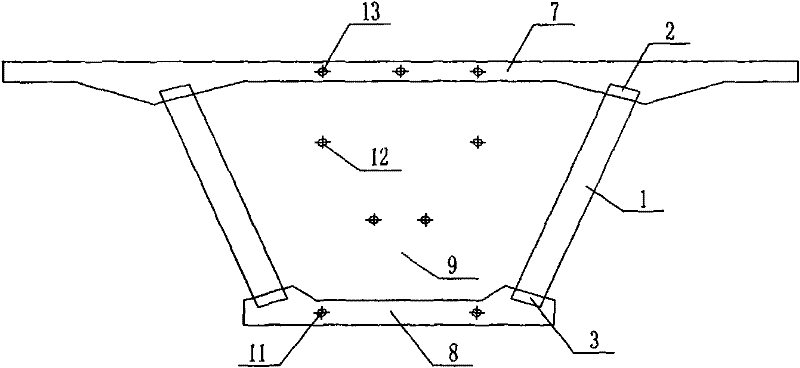
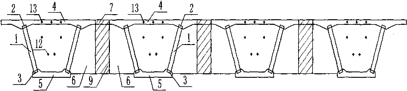
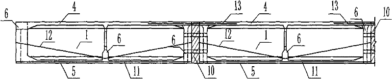
[0021] Such as Figure 3-6 Shown: a corrugated steel web prestressed concrete continuous box girder. Concrete beams or diaphragms 6 and prestressed tendons 11 in the bottom plate. The upper connector 2 is located on the upper end of the corrugated steel web 1 . It is welded and fixed with the corrugated steel web 1 and embedded in the precast concrete roof 4 . The upper connector 2 consists of an upper wing plate, double-holed steel ribs, and transverse perforated steel bars. The upper wing plate is made of steel. Pass through the openings of the double-opened steel ribs. The lower connecting piece 3 is located at the lower end of the corrugated steel web 1 and is embedded in the precast concrete bottom plate 5 . The lower connector 3 can be a hole at the bottom of the corrugated steel we...


PUM


Abstract

The invention discloses a corrugated steel web prestressed concrete continuous box girder. In the box girder, after being fixedly connected with a corresponding steel bar in a cast-in-place member, transverse steel bars of a precast concrete top plate, a precast concrete bottom plate and a precast concrete beam or a precast concrete diaphragm plate of two adjacent corrugated steel web prestressed concrete flanged beam units which are erected are connected by a cast-in-place concrete top plate between the adjacent precast concrete top plates, a cast-in-place concrete bottom plate between the adjacent precast concrete bottom plates and a cast-in-place concrete beam or a cast-in-place concrete diaphragm plate between the adjacent precast concrete beams or precast concrete diaphragm plates to form closed box girders; and external prestressed bars in the closed box girders are pulled and anchored, the closed girders corresponding to two adjacent holes are connected by pouring cast-in-place concrete longitudinal beams, hogging moment prestressed bars on pillar tops are pulled and anchored, and temporary supports are removed to form the continuous box girder. The corrugated steel web prestressed concrete continuous box girder has the characteristics of high stressed performance, high utilization rate of materials and obvious economic benefit, and is easy and convenient to construct.

Description

technical field [0001] The invention belongs to the technical field of road and railway bridges, and mainly relates to a corrugated steel web prestressed concrete continuous box girder and a construction method. Background technique [0002] Prestressed concrete box girder with corrugated steel web is a new type of steel-concrete composite structure, making full use of the advantages of concrete compression resistance and high shear yield strength of corrugated steel web, effectively combining steel and concrete , which improves the use efficiency of materials, and is an economical, reasonable and efficient structural form. The existing corrugated steel web prestressed concrete box girder usually adopts two construction methods of cast-in-place and prefabricated installation. [0003] Such as figure 1 Shown: The corrugated steel web prestressed concrete box girder member constructed by the cast-in-place method is mainly composed of corrugated steel web 1, upper connector 2...

Claims


Application Information

Patent Timeline
Patent Type & Authority Applications(China)
IPC IPC(8): E01D19/00E01D21/00
Inventor 汤意李宏瑾吴继峰刘江周恒乐艺
Owner HENAN PROVINCIAL COMM PLANNING & DESIGN INST CO LTD
Why Eureka
Try Eureka