Continuous box girder made of corrugated steel web pre-tensioned prestressed concrete and construction method

A corrugated steel web and precast concrete technology, which is applied in bridges, bridge materials, bridge construction, etc., can solve problems affecting construction quality and structural durability, affecting material utilization, and insufficient bearing capacity of prestressed concrete continuous girder bridges.

Inactive Publication Date: 2012-09-26
HENAN PROVINCIAL COMM PLANNING & DESIGN INST CO LTD
View PDF9 Cites 19 Cited by
  • Summary
  • Abstract
  • Description
  • Claims
  • Application Information

AI Technical Summary

Problems solved by technology

However, the process of forming holes, threading beams, and grouting is complicated, and the construction period is relatively long, and problems such as hole plugging, inaccurate grouting, and out-of-control prestress may occur, which will affect the construction quality and the durability of the structure.
The bonded prestressed concrete reduces the tensile stress of the prestressed steel bars due to the bond resistance, resulting in a decrease in the compressive stress of the concrete. The anchorage is permanently buried in the structure and cannot be reused, which affects the material utilization rate.
If the grouting process is improper and moisture intrudes, the prestressed steel may be corroded or even broken, resulting in insufficient bearing capacity, cracks and continuous deflection of the prestressed concrete continuous girder bridge.

Method used


Image

  • Continuous box girder made of corrugated steel web pre-tensioned prestressed concrete and construction method
  • Continuous box girder made of corrugated steel web pre-tensioned prestressed concrete and construction method
  • Continuous box girder made of corrugated steel web pre-tensioned prestressed concrete and construction method

Examples


Embodiment Construction

[0024] In conjunction with the accompanying drawings, the following embodiments of the present invention are given, but the present invention is not limited to the following embodiments.

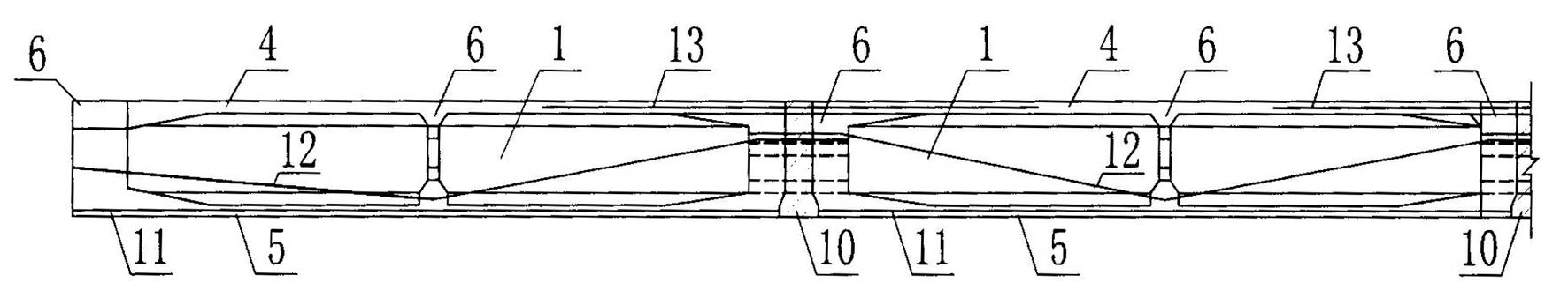
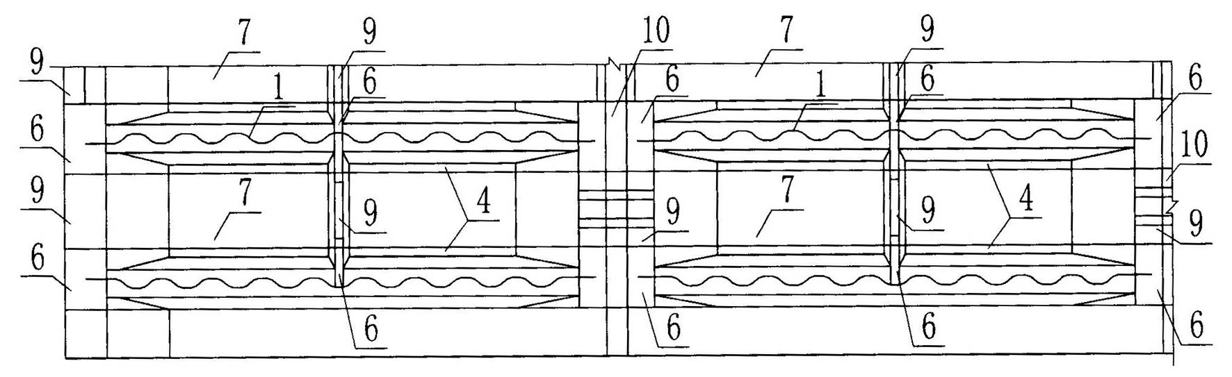
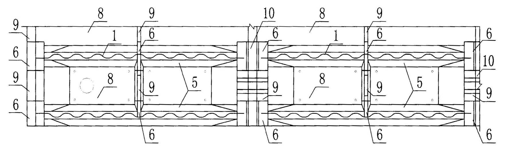
[0025] Such as Figure 1~4 Shown: A corrugated steel web pretensioned prestressed concrete continuous box girder includes multiple prefabricated I-beam units arranged in the transverse and longitudinal directions of the bridge. Among them, there are at least two horizontal spans and at least two vertical spans. In this way, at least four I-beams are required to form a two-span single-box single-room continuous box girder. Similarly, multi-span continuous box girders can be formed. When the bridge is wider, more than four I-beams are needed to form more than two box girders in each horizontal span.

[0026] Such as Figure 5As shown: each I-beam unit is mainly composed of corrugated steel web 1, upper connector 2, lower connector 3, precast concrete roof 4, precast concrete bottom slab 5, p...


PUM


Abstract

The invention discloses a continuous box girder made of corrugated steel web pre-tensioned prestressed concrete. A plurality of I-shaped beam elements precast by a plurality of corrugated steel web pre-tensioned prestressed concrete are erected and installed on an abutment, precast concrete top plates, precast concrete bottom plates, and transverse reinforcements of precast concrete beams or diaphragm plates of each two adjacent I-shaped beam elements are fixedly connected with reinforcing steel bars in corresponding cast-in-place members, and then a cast-in-place concrete top plate between each two adjacent precast concrete top plates, a cast-in-place concrete bottom plate between each two adjacent precast concrete bottom plates and a cast-in-place concrete beam or transverse diaphragm plate between each two adjacent precast concrete beams or transverse diaphragm plates are connected with one another to form closed box girders. Each two adjacent closed box girders are connected with each other by pouring cast-in-place concrete longitudinal beams, thus forming the continuous box girder. Pre-tensioned prestressed tendons are arranged in bottom plate bodies of the precast I-shaped beam elements; and pier top hogging moment prestressed tendons are arranged in the cast-in-place concrete top plates of the closed box girders.

Description

technical field [0001] The invention belongs to the technical field of road and railway bridges, and mainly relates to a corrugated steel web pretensioned prestressed concrete continuous box girder and a construction method. Background technique [0002] Prestressed concrete box girder with corrugated steel web, as a new type of steel-concrete composite structure, makes full use of the advantages of concrete compression resistance and high shear yield strength of corrugated steel web, effectively combining steel and concrete , which improves the use efficiency of materials, and is an economical, reasonable and efficient structural form. [0003] "A prestressed concrete continuous box girder with corrugated steel web" (Patent No.: ZL201120098134.3) which the applicant has applied for is compared with the two common construction methods of existing support or cantilever cast-in-place and prefabricated installation. The structural advantages of corrugated web prestressed concr...

Claims


Application Information

Patent Timeline
Patent Type & Authority Applications(China)
IPC IPC(8): E01D2/04E01D21/00E01D101/28
Inventor 汤意李宏瑾李华强吴继峰乐斐李雯乐艺
Owner HENAN PROVINCIAL COMM PLANNING & DESIGN INST CO LTD
Why Eureka
Try Eureka