Connector, connector system and method of making a connector

Inactive Publication Date: 2000-03-28
SMITHS INTERCONNECT AMERICAS INC
View PDF7 Cites 99 Cited by
  • Summary
  • Abstract
  • Description
  • Claims
  • Application Information

AI Technical Summary

Benefits of technology

to provide such a connector and array that can be

Problems solved by technology

An aspect of the contacts and contact arrays of the Barahi et al. patent is that the embodiment disclosed there, while suitable from a cost standpoint to fabricatio

Method used


Image

  • Connector, connector system and method of making a connector
  • Connector, connector system and method of making a connector
  • Connector, connector system and method of making a connector

Examples


Embodiment Construction

, taken together with the drawings, in which:

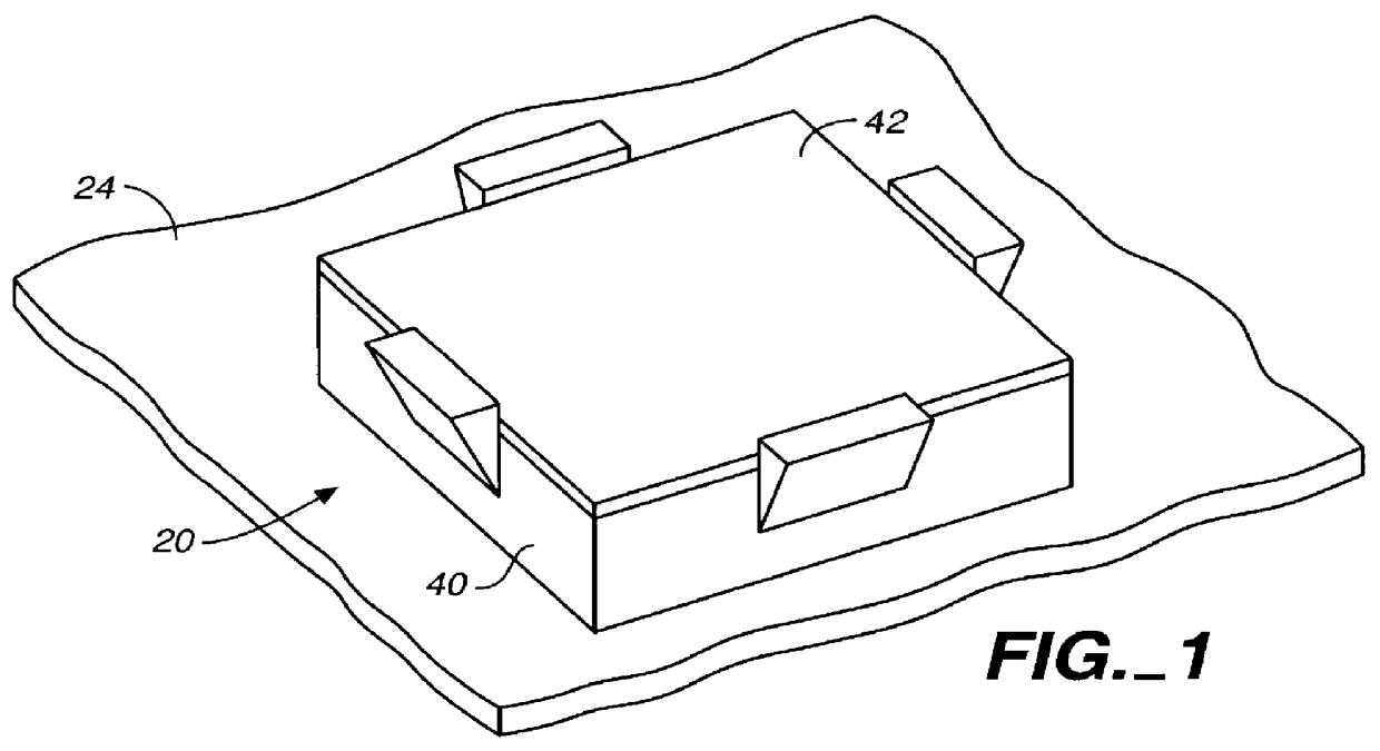
FIG. 1 is an external perspective view of a connector system in accordance with the invention.

FIG. 2 is an exploded perspective view of the connector system shown in FIG. 1.

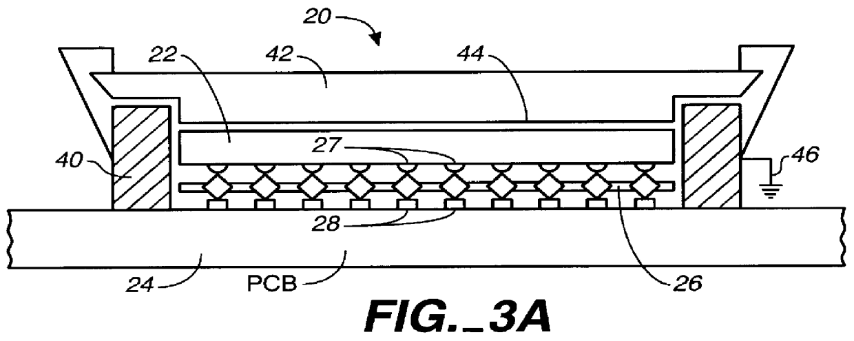
FIG. 3A is a side view of the connector system of FIGS. 1-2 in assembled form.

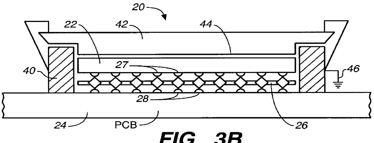
FIG. 3B is a side view of an alternative embodiment of the connector system in FIG. 3A.

FIGS. 4A-4D are enlarged perspective views of a portion of the connector system shown in FIGS. 1-3A.

FIGS. 5A-5C are plan views of portions of the connector system shown in FIGS. 4A-4D in different stages of fabrication.

FIG. 5D is an enlarged fragmentary view in cross-section of the planar material which is comprised of the planar conductive layer or body in which conductor cells are formed and the insulating layers on each side of the conductive layer.

FIGS. 6A-6B are plan views of portions of two further embodiments of a connector system in accordance with the invention.

FIG. 7 is an enlarged perspective vie...


PUM


Abstract

A connector system (20) connects a leadless integrated circuit (IC) device (22) to a printed circuit (PC) board (24) by means of a contact array (26). The contact array (26) connects input-output (I/O) contacts on the IC device (22) to corresponding circuit contacts (28) on PC board (24). The contact array (26) is a generally thin, flexible and rectangular shaped element that is sandwiched between the PC board (24) and the IC device (22). The contact array (26) has a plurality of square cells (30) that are each a portion of the array (26) and are formed from a planar body (32) of a suitable conductive material, such as beryllium copper, sandwiched between suitable insulating films, formed from polyimide. Each cell is divided into a first pair (34) of contact elements (36) extending above the plane of the body (32) and a second pair (38) of contact elements (36) extending below the plane of the body (32).

Description

1. Field of the InventionThe present invention relates generally to interconnect technology. More particularly, it relates to a form of interconnect technology that is usable both for testing integrated circuits and for permanently interconnecting in solderless connections with the integrated circuits at a system level on a printed circuit (PC) board. Most especially, in a preferred form, the invention relates to an improved form of contacts and contact arrays described or claimed in commonly assigned Barahi et al., U.S. Pat. No. 5,629,837, issued May 13, 1997.2. Description of the Prior ArtThe contacts and contact arrays in the above referenced issued patent represent a significant advance in contact structure intended primarily for electrical test applications. The contacts and contact arrays of that patent are particularly well able to withstand repeated insertion and withdrawal of integrated circuits from a test fixture incorporating them.An aspect of the contacts and contact ar...

Claims


Application Information

Patent Timeline
IPC IPC(8): H01R13/24H01R13/22
CPCH01R13/2407H01R13/2464H01R12/7076
Inventor JONAIDI, SIAMAK
Owner SMITHS INTERCONNECT AMERICAS INC
Why Eureka
Try Eureka