Hydrogen production from hydro power

a technology of hydropower and hydropower, which is applied in the direction of electric generator control, greenhouse gas reduction, instruments, etc., can solve the problems of escalating fuel extraction costs, affecting the safety of transportation and long-term storage of spent fuel, and affecting the safety of the transportation of spent fuel

Inactive Publication Date: 2005-01-11
VOITH SIEMENS HYDRO POWER GENERATION
View PDF55 Cites 69 Cited by
  • Summary
  • Abstract
  • Description
  • Claims
  • Application Information

AI Technical Summary

Benefits of technology

Yet another embodiment of the present invention relates to a method for performing an economic comparison analysis in a hydroelectric power generating facility. The facility includes a turbine driven power generating unit receiving a flow of water through an upstream conduit to generate electrical power. The facility is capable of operating in a first operating mode wherein the generated electrical power is transported away from the facility using a first energy carrier. The facility is also capable of operating in a second operating mode wherein the generated electrical power is transported away from the facility using a second energy carrier. The method comprises computing a first economic value for the generated electrical power when the first energy carrier is used, and computing a second economic value for the generated electrical power when the second energy carrier is used. The method further comprises comparing the first economic value with the second economic value to identify the operating mode that provides the higher economic value, and operating the turbine facility in the identified operating mode.

Problems solved by technology

However, these energy sources all have significant disadvantages including pollution, periodic shortages and escalating costs of extracting the fuels.
Although at one time it was thought that nuclear fission power could provide an answer to these problems, that has not proved out.
Not only are there significant concerns regarding the safety of operating the existing nuclear systems, but there is also the significant problem of the safe transportation and long term storage of the spent fuel.
However, that is not to say these technologies are without difficulties.
For example, one difficulty with these technologies is that the underlying energy sources (i.e., wind, sunlight and water) can be subject to periodic swings in availability, e.g., the sun may eclipse, the winds may subside, and the water levels may fall due to extended periods of drought.
Another difficulty is that the best locations for capturing the foregoing energy sources are often remote from where the energy is used.
However, this may not be the most efficient use of the generated energy from an economic standpoint.
As is well known, connecting a wind or hydro powered turbine generator to a utility grid imposes certain constraints on the generator.
When this occurs, the energy that could be captured is simply wasted.
Although various energy storage systems (e.g., battery storage or pumped hydro-energy storage) can be utilized to overcome this problem, such systems are relatively expensive to install and result in efficiency losses of their own due to the repeated energy conversions.
Although using hydrogen as a carrier of energy generated from solar, wind and hydro installations avoids the aforementioned constraints imposed by using a utility grid to carry the energy, it also may not be the most efficient use of the generated energy from an economic standpoint.
As is well known, the prices of electrical energy continuously fluctuate due to changing demand levels, both due to seasonal variations and time of day restrictions.
Similarly, the price of hydrogen is also impacted by changing demand levels and seasonal variations.

Method used


Image

  • Hydrogen production from hydro power
  • Hydrogen production from hydro power
  • Hydrogen production from hydro power

Examples


Embodiment Construction

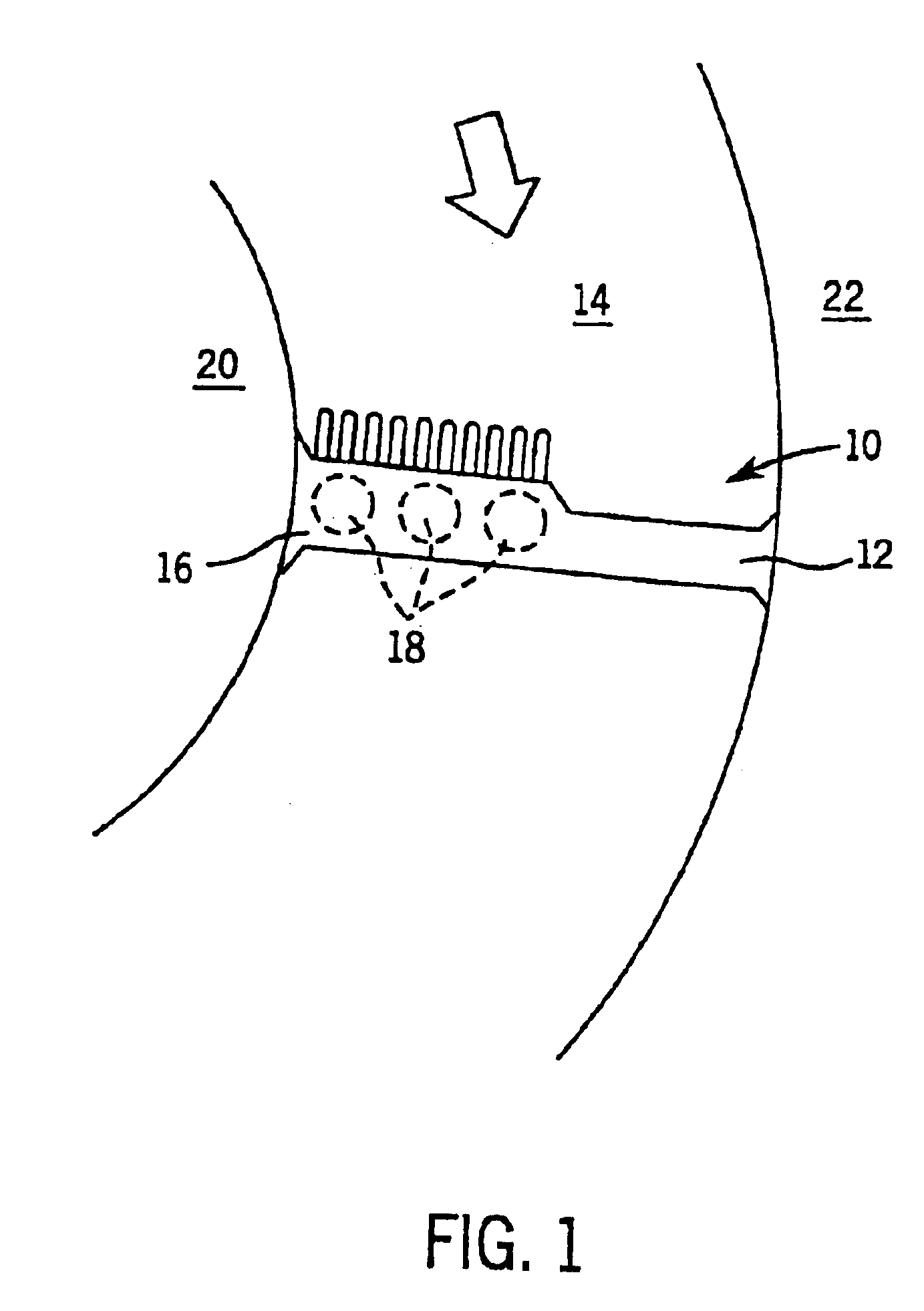
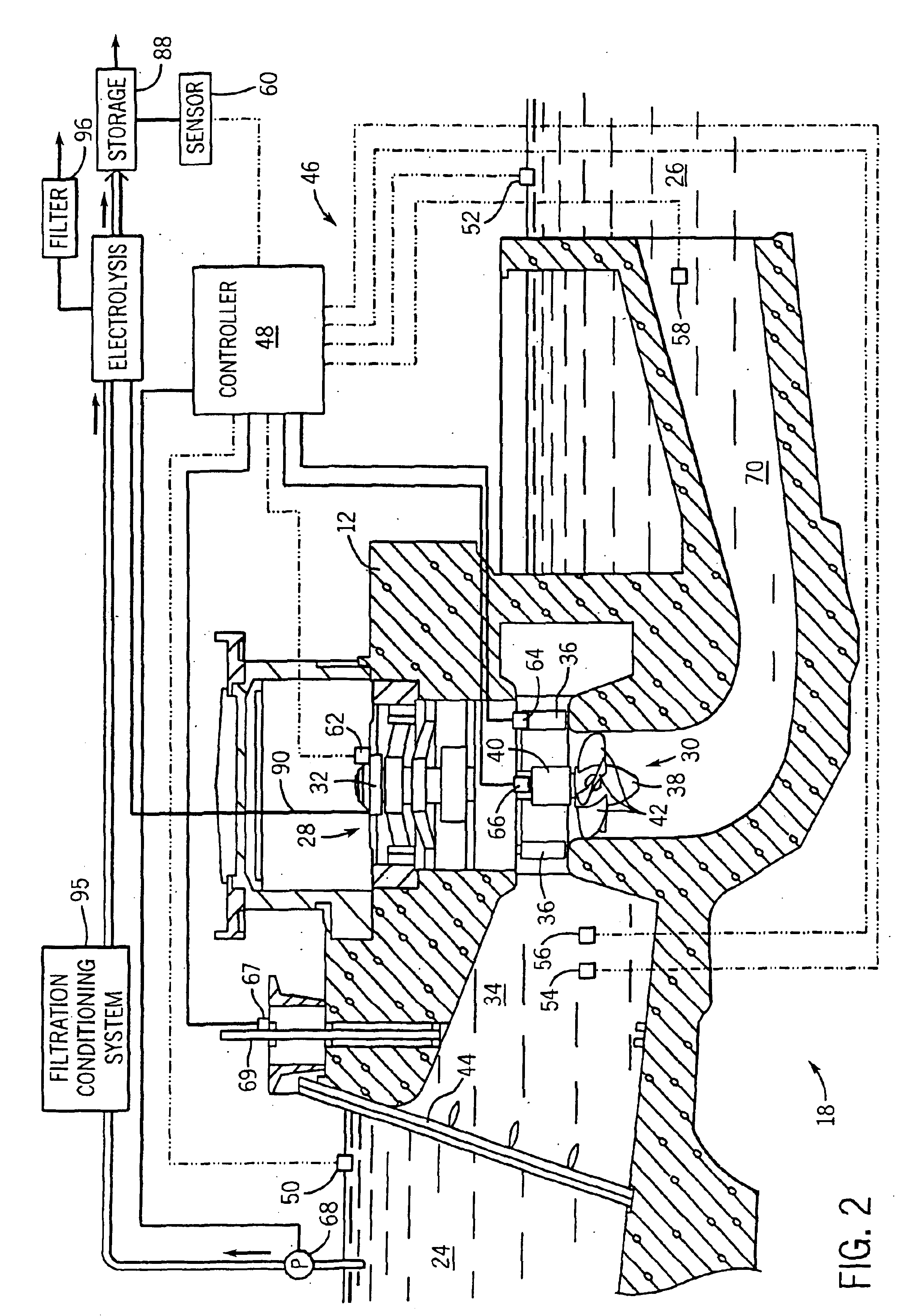
Turning now to the drawings and referring to FIG. 1, a hydroelectric power generating installation 10 is illustrated generally, including a dam 12 spanning a river 14 and a power generating facility 16. In the illustrated embodiment, facility 16 includes a series of three turbine generating units, each designated generally by the reference numeral 18. As will be understood by persons skilled in the art, facility 16 may include more or fewer generating units 18, and such units may be situated adjacent to one or both banks 20, 22 of river 14, or at various locations between the banks. Moreover, while the following discussion makes reference to a Kaplan turbine by way of example, the present invention is not limited to application with any particular type of turbine unit. For example, other types of turbines that may be suitable for use in facility 16 besides Kaplan units include Francis, Pelton, Turgo, bulb, propeller, tubular, and crossflow turbines.

Each turbine unit 18 may be of gen...


PUM


Abstract

A method is provided for operating a hydroelectric power generating facility configured for operating in first and second operating modes. The facility includes a turbine driven power generating unit receiving a flow of water through an upstream conduit to generate electrical power. The method comprises computing a first economic value for the generated electrical power when operating in the first operating mode, and computing a second economic value for the generated electrical power when operating in the second operating mode. The method further comprises comparing the first economic value with the second economic value to identify the operating mode that provides the higher economic value, and operating the turbine facility in the identified operating mode.

Description

FIELD OF THE INVENTIONThe present invention relates to the field of hydrogen production from hydroelectric power. More particularly, the invention relates to the high volume production of hydrogen from large scale hydroelectric power dam installations. The invention further relates to a technique for performing an economic analysis to determine when to operate the hydroelectric power dam installation in a hydrogen production mode.BACKGROUND OF THE INVENTIONMost energy produced today is derived from fossil fuels such as oil, coal and natural gas. However, these energy sources all have significant disadvantages including pollution, periodic shortages and escalating costs of extracting the fuels. Although at one time it was thought that nuclear fission power could provide an answer to these problems, that has not proved out. Not only are there significant concerns regarding the safety of operating the existing nuclear systems, but there is also the significant problem of the safe trans...

Claims


Application Information

Patent Timeline
Patent Type & Authority Patents(United States)
IPC IPC(8): F03B3/00F03B3/06F03B13/00F03B15/00
CPCF03B3/06F03B13/00G06Q50/06F05B2220/61Y02E70/10Y02E10/223Y02E60/366Y02E10/20Y02E60/36Y02P70/50F03B15/00
Inventor MAIWALD, MARCOMULLER, BERTRAM KURT
Owner VOITH SIEMENS HYDRO POWER GENERATION
Why Eureka
Try Eureka