Method and apparatus for evaluating prothrombotic conditions

a prothrombotic condition and prothrombotic technology, applied in the field of blood analysis, can solve the problems of patient deaths at st, numerous opportunities for error, and statistically and clinically significant differences in inr

Inactive Publication Date: 2010-09-16
CARROLL WALLACE E +1
View PDF0 Cites 10 Cited by
  • Summary
  • Abstract
  • Description
  • Claims
  • Application Information

AI Technical Summary

Benefits of technology

[0029]According to embodiments of the invention relating to the determination of a hypercoagulable condition, the method and apparatus further may include monitoring a voltage signal of a spectrophotometer to determine fibrinogen to fibrin formation in conjunction with or association with the readings taken of the sample to evaluate the passage and/or absorption of particular wavelengths or a spectral range.
[0030]According to preferred embodiments, the method and apparatus may be used to determine hypercoagulab

Problems solved by technology

The authors observed that a change in the thromboplastin reagent can result in statistically and clinically significant differences in the INR.
Considering the current methods for determining anticoagulant therapy factors, there are numerous opportunities for error.
For example, it has been reported that patient deaths have occurred at St.
There the problem did not appear to be the thromboplastin reagent, but rather, was apparently due to a failure to enter the correct ISI in the instrument, used to carry out the prothrombin times when the reagent was changed.
This resulted in the incorrect INR's being reported.
Doses of coumadin were given to already overanticoagulated patients based on the faulty INR error, and it is apparent that patient deaths were caused by excessive bleeding due to coumadin overdoses.
But even in addition to errors where a value is not input correctly, the known methods for determining anticoagulant therapy factors still may be prone to errors, even when the procedure is carried out in accordance with the reagent manufacturer's ISI data.
This error is apparently what physicians must work with when treating patients.
The presence' of too much free t

Method used


Image

  • Method and apparatus for evaluating prothrombotic conditions
  • Method and apparatus for evaluating prothrombotic conditions
  • Method and apparatus for evaluating prothrombotic conditions

Examples


Embodiment Construction

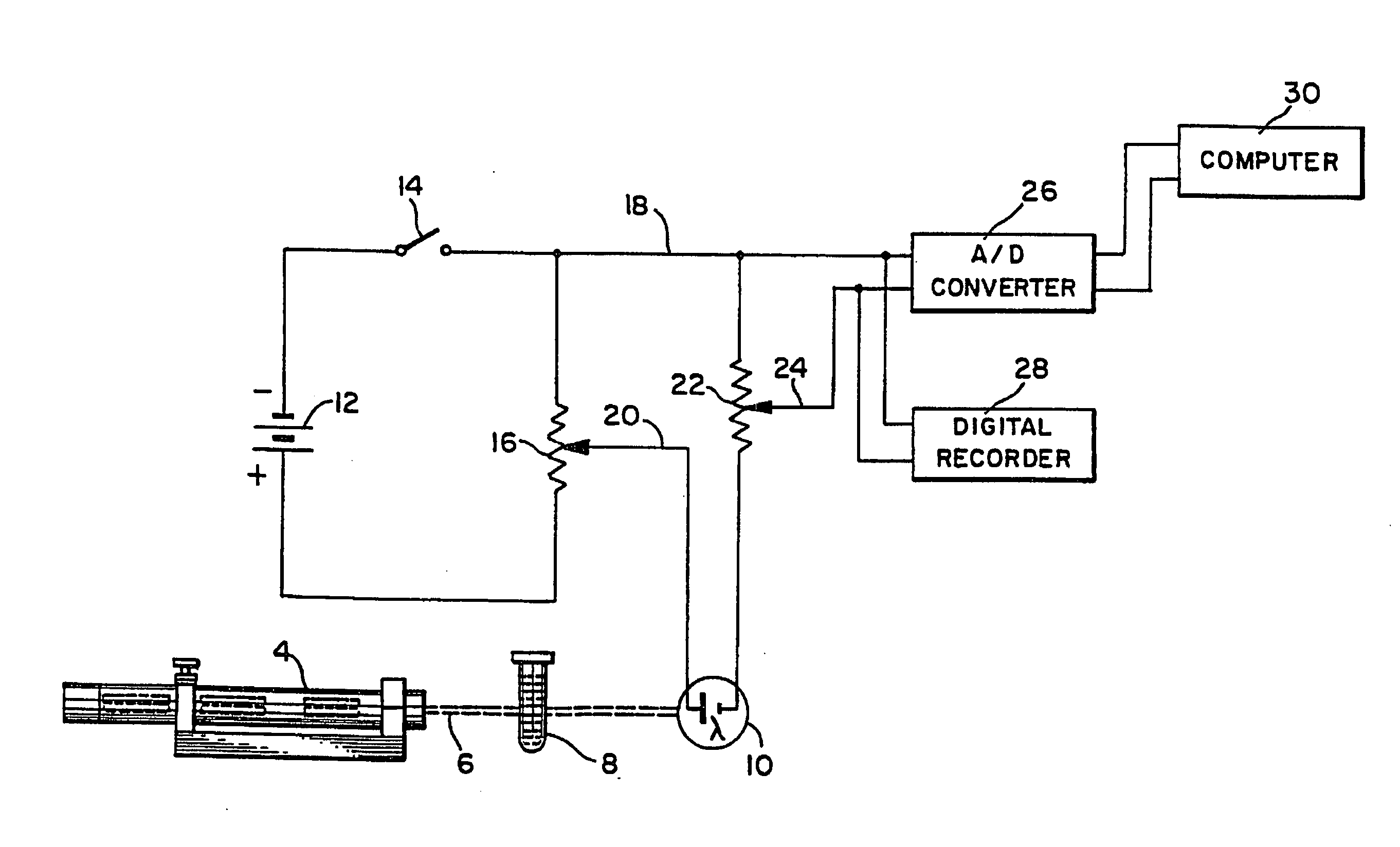
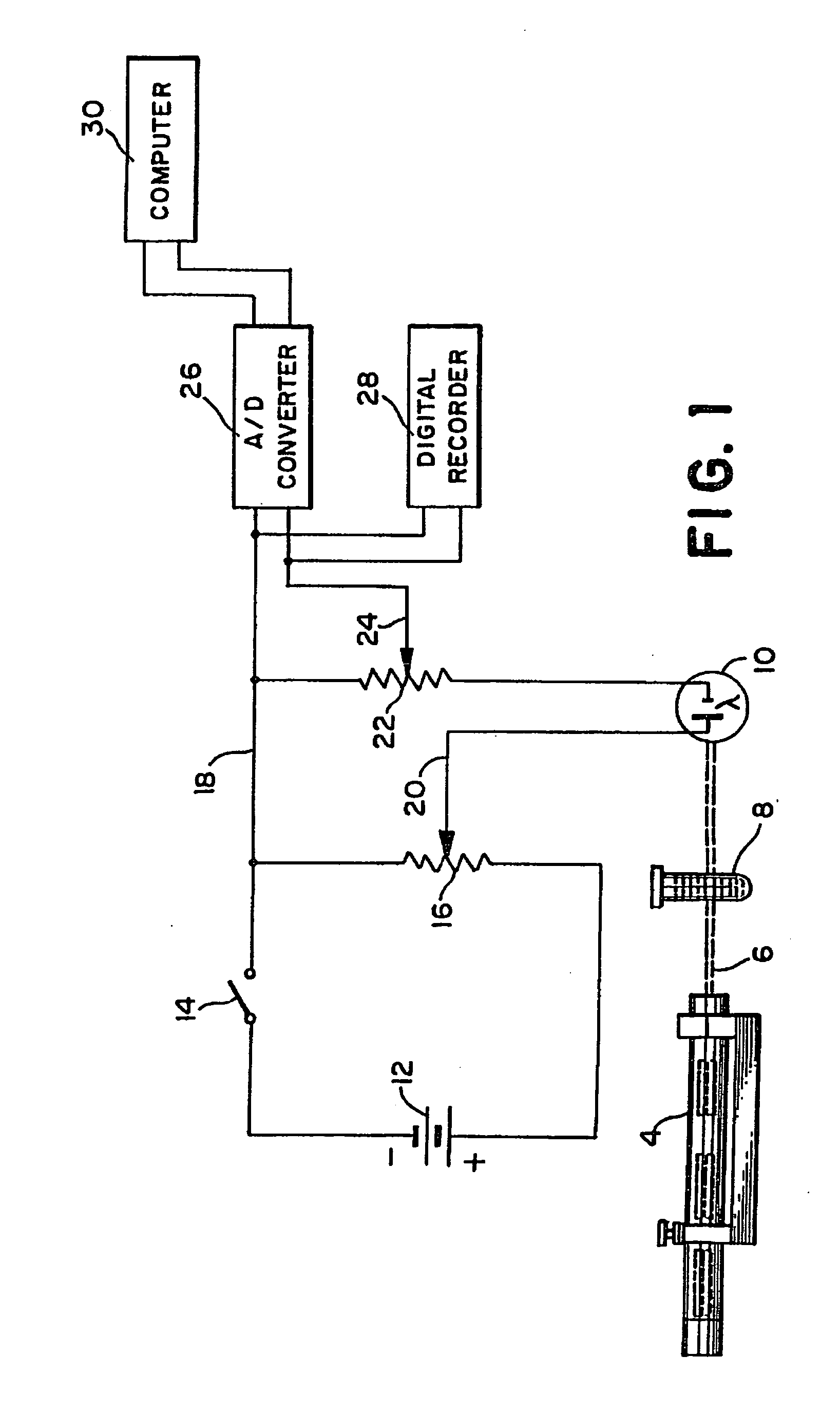
[0039]Referring to the drawings, wherein the same reference numbers indicate the same elements throughout, there is shown in FIG. 1 a light source 4 which may be a low power gas laser, or other light producing device, producing a beam of light 6 which passes through a sample test tube, such as the container 8, and is received by detection means which is preferably a silicon or selenium generating photocell 10 (photovoltaic cell). Battery 12 acts as a constant voltage DC source. Its negative terminal is connected through switch 14 to one end of variable resistor 16 and its positive terminal is connected directly to the opposite end of variable resistor 16. The combination of battery 12 and variable resistor 16 provides a variable DC voltage source, the variable voltage being derivable between line 18 at the upper terminal of resistor 16 and wiper 20. This variable DC voltage source is connected in series with detection means photocell 10, the positive output of detection means photoc...


PUM


Abstract

Methods and apparatus are disclosed for determining a prothombotic condition, including a condition of hypercoagulability. The determination is based on the clotting of a sample of blood or blood components which involves reacting the sample with a clotting agent and recording time and absorbance values. A slope determination is utilized to determine an indicator for a prothrombotic condition. The indicator according to embodiments, may be determined through the derivation of an angle in conjunction with the clotting analysis and slope.

Description

CROSS-REFERENCE TO RELATED APPLICATIONS[0001]This application is a continuation-in-part of U.S. application Ser. No. 11 / 359,667, filed on Feb. 22, 2006, issued as U.S. Pat. No. 7,276,377 on Oct. 2, 2007, which is a continuation-in-part of U.S. application Ser. No. 10 / 662,043, filed on Sep. 12, 2003, which is a continuation of U.S. application Ser. No. 10 / 428,708 filed on May 2, 2003; the application also claims priority to U.S. Provisional application Ser. No. 60 / 679,423, filed on May 10, 2005, the disclosures of which are herein incorporated by reference.BACKGROUND OF THE INVENTION[0002]1. Field of the Invention[0003]This invention relates to analyzing blood for carrying out coagulation studies and other chemistry procedures, including determining the presence of prothrombotic abnormalities such as conditions of hypercoagulability, and monitoring oral anticoagulant therapy to take into account the platelet count in determining prothrombin times (PT), and a new Anticoagulant Therapy...

Claims


Application Information

Patent Timeline
IPC IPC(8): G06F19/00G01N33/48G16H10/40G16H20/40
CPCG06F19/3481G01N2021/825G01N33/86G01N21/82G16H20/40G16H10/40
Inventor CARROLL, WALLACE E.JACKSON, R. DAVID
Owner CARROLL WALLACE E
Why Eureka
Try Eureka