
Super-large scale photon capture bioreactor for water purification and operation method therefor

a photon capture and bioreactor technology, applied in the field of bioreactors, can solve the problems of high cost, high maintenance cost, and inconvenient operation and management, and achieve the effect of low cost and small floor area

Active Publication Date: 2018-02-08
PHOTON ECO CAPTURE
View PDF4 Cites 9 Cited by
  • Summary
  • Abstract
  • Description
  • Claims
  • Application Information

AI Technical Summary

Benefits of technology

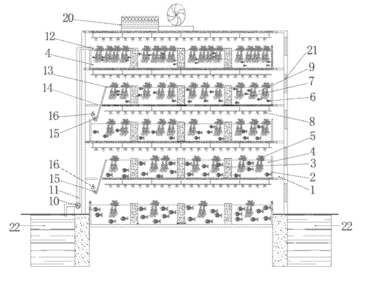
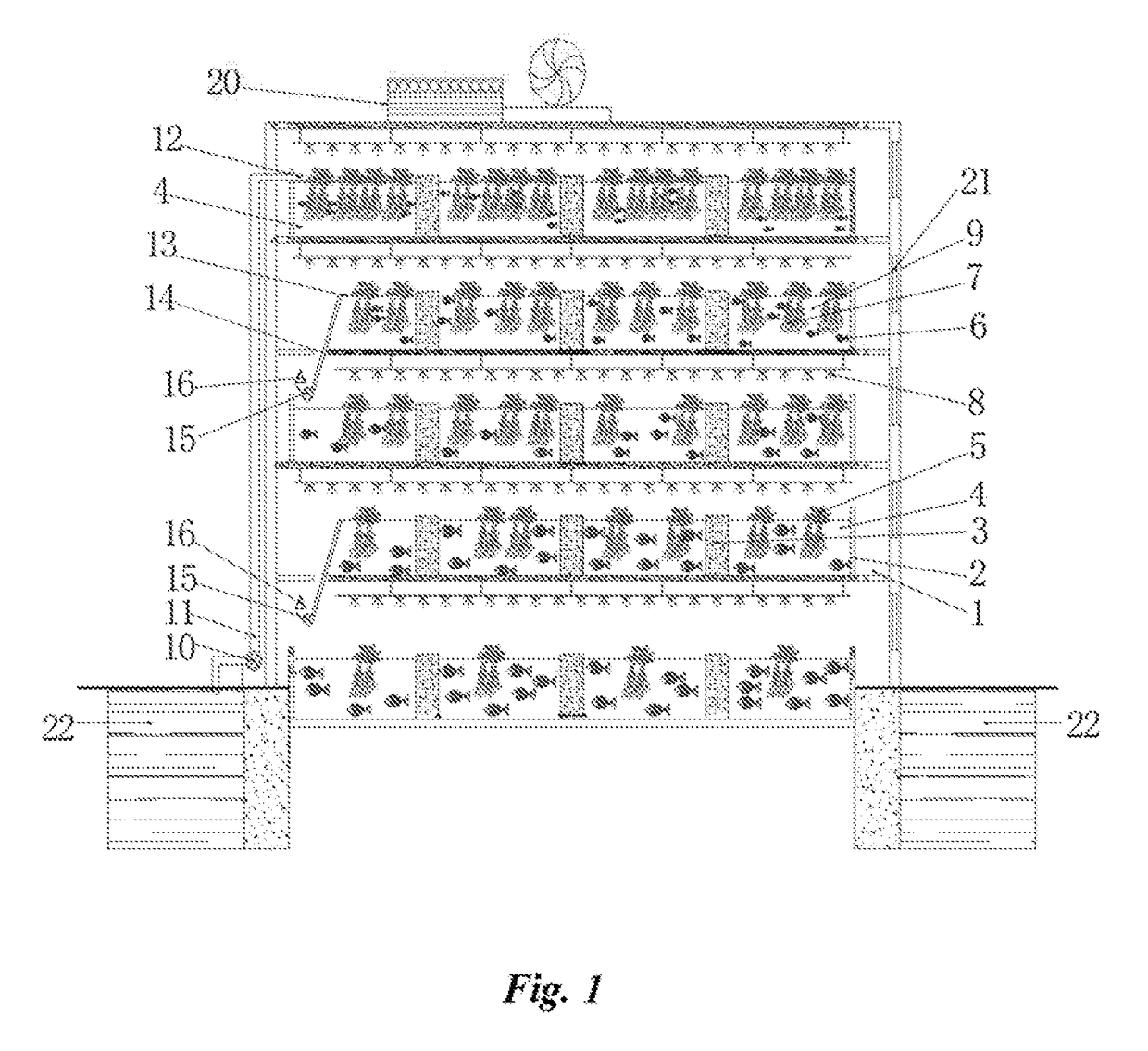
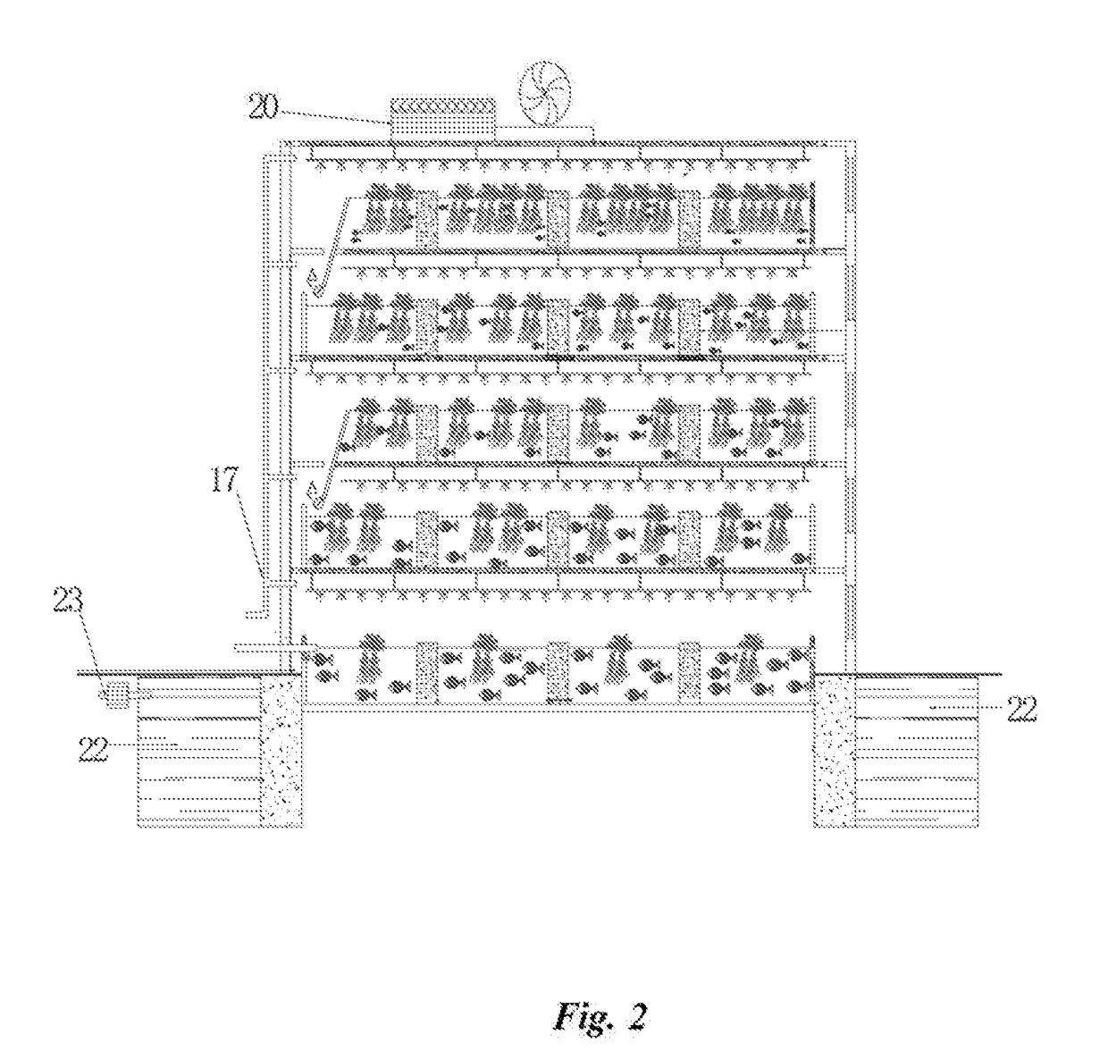
The present invention provides a large scale photon capture bioreactor for water purification that is easy to control, stable quality, takes minimal floor space, operates at low cost, has low energy consumption, and produces economic benefits. The bioreactor has a multi-layered structure that intensifies the process of water purification and reduces the occupied area and cost of construction. The organisms inside the bioreactor require no high energy consumption equipment and can output energy sources for self-supplementation. The plants and animals inside the bioreactor can be harvested and utilized for power generation. The ecological production industry formed by the purified water and harvested organisms has high economic value.

Problems solved by technology

Compared with some traditional biological treatment processes, the membrane bioreactor has major advantages of higher effluent quality and stability, less excess sludge, small floor space, and higher removal efficiency of ammonia nitrogen and refractory organics, however, on the other hand, the membrane bioreactor also has major disadvantages of higher cost, membrane fouling and membrane plugging, inconvenience for operation and management, higher energy consumption, and higher maintenance cost.
The defects of the membrane bioreactor induced that it is difficult to popularly apply to large-scale sewage treatment plants.
Up to now, traditional sewage treatment technologies either consume large amount of energy source, or occupy large area.
The traditional treatment process becomes a heavy burden.
In addition, the cleanliness of drinking water directly affects the health of the general public.
The existing main problem of drinking water in high oxygen consumption.
High oxygen consumption means that too much organic matters involved in drinking water.
But the water disinfection will increase by-products which can increase mutagenic activity of water, thus having a long-term negative impact on human health.
Features of harm of the organic matters on health often are lagging.
For sewage treatment, one fundamental drawback of the traditional processing method is utilizing equipment with high energy consumption to resist potential energy and resources in the water.
In traditional aerobic biological treatment processes, contaminants may volatilize easily along with the aeration air flow, gas stripping phenomenon occurs, so that not only the treatment effect is very unstable, but also cause air pollution.
Adding oxygen using physical methods, flocculation and sedimentation using chemical methods, biological anaerobic reaction or aerobic reaction method are used to treat one cubic meter of sewage will result in a very high energy consumption.
At that time, energy consumption on sewage treatment will become a heavy burden.
However, this technology encountered greater resistance due to large occupied area and limited decontamination capacity.
1) Huge energy consumption resulting in unsustainability;
2) Even if all of the processing in accordance with the requirements of discharge standards, diluted ecological water no longer exists;
3) The high cost of wastewater treatment become a lifelong burden on the general public.
4) Purification and treatment taking up a lot of land but not to create economic wealth, squeezing the living space.

Method used


Image

  • Super-large scale photon capture bioreactor for water purification and operation method therefor
  • Super-large scale photon capture bioreactor for water purification and operation method therefor
  • Super-large scale photon capture bioreactor for water purification and operation method therefor

Examples


application examples

[0067]An application example is illustrated for a three-stage purification treatment project with daily treatment of 10,000 tons which can meet one-class A permitted criteria. According to current common processes, the project will cover an area of about 20,000 square meters, while the super-large scale photon capture bioreactor only covers an area of 3500 square meters (50×70 m). A volume of the super-large scale photon capture bioreactor (a height of the closed building is 15 m) is 3.6 cubic meters (40×60×15). A total investment budget including devices and equipment (such as generators) for the super-large scale photon capture bioreactor can be about 0.230.3 billion (excluding land costs).

[0068]Each biological reaction layer has a width of 40 m and a length of 60 m. Each biological reaction layer can build with 20 water ditches each having a depth of 1.2 m, a width of 2 m and a length of 60 m (each layer can be divided evenly into 20 portions). A water inlet of each water ditch i...


PUM

PropertyMeasurementUnit
depthaaaaaaaaaa
concentrationaaaaaaaaaa
CODaaaaaaaaaa

Abstract

A super-large scale photon capture bioreactor for water purification and aquaculture, includes a sealable three-dimensional room. Circuitous water ditches (2) at each layer inside the room. The water ditches (2) within a layer includes an inlet (12) and an outlet (13). A plurality of filter units (4) are at intervals in water ditches (2) at each layer. Float-planted plants (5) are on water surface of each filter unit, aquatic animals (6) and microorganisms (7) are underwater, and plant growth illustrating lights (8) are above float-planted plants (5) at adjustable height. A vane wheel (15) connecting a generator (16) is under an outlet (13) of an upper layer. A water inlet (12) of a next layer is under the vane wheel (15). Water to be purified is guided to an inlet (12) at an uppermost layer. The bioreactor is in low energy consumption, less occupied area, no pollution and clean production.

Description

TECHNOLOGY FIELD[0001]The present invention generally relates to bioreactors, and particularly to Large Scale Photon Capture Bioreactor (LSPECBR) for water purification.BACKGROUND OF THE INVENTION[0002]The Bioreactor is a biological engineering technology began in 1980s, and refers to any manufacturing device or engineering device for providing biological activity environment. The bioreactors are devices or systems use biological functions of bio-organisms, to obtain target products, cells, tissues and organs, etc. by biochemical reaction or biological metabolism in vitro or in vivo, and are reactors related to biological or biochemical active material production out of the reaction process by specific biological. These bioreactors generally in cylindrical shape and the volume ranges of from a few litres to several cubic meters, and generally made up of stainless steel.[0003]The bioreactor technology has gone through three stages: bacterial bioreactors, cell bioreactors and transgen...

Claims


Application Information

Patent Timeline
Patent Type & Authority Applications(United States)
IPC IPC(8): C02F3/32A01G7/02A01G7/04A01K63/04A01G31/02
CPCC02F3/327A01K63/045A01G31/02A01G7/045A01G7/02A01K61/10Y02W10/37C02F2209/001C02F2209/40C02F2303/10A01K63/04Y02W10/30A01G31/00C02F1/001Y02P60/60Y02W10/10A01K63/00C02F3/32B01D24/34C02F1/30C02F3/06C02F3/102C02F9/00
Inventor Y HU, JAMES
Owner PHOTON ECO CAPTURE
Learn More