Method and apparatus for controlling a submergible pumping system

a pumping system and submerged technology, applied in the direction of pump control, motor parameter, rotary piston liquid engine, etc., can solve the problems of insufficient pressure, less than satisfactory performance, and the head of centrifugal pumps may not develop enough pressure to adequately displace fluids

Inactive Publication Date: 2000-04-04
CAMCO INT
View PDF5 Cites 162 Cited by
  • Summary
  • Abstract
  • Description
  • Claims
  • Application Information

AI Technical Summary

Problems solved by technology

However, in many production wells pressures are insufficient to raise the production fluids to an above-ground collection point.
While in many applications such pumps provide sufficient lift and adequate efficiencies, a number of applications exist where their performance is less than satisfactory.
In particular, in wells producing heavy or viscous fluids, centrifugal pumps may not develop sufficient pressure head to adequately displace the fluids through the production conduit.
However, because centrifugal pumps are typically inefficient at lower speeds, their use in submergible pumping systems may limit the range of production rates available to the well operator, particularly at low speeds.
However, unlike centrifugal pumps, which have very low starting torques that can be provided directly by a submergible electric motor, progressive cavity ...

Method used


Image

  • Method and apparatus for controlling a submergible pumping system
  • Method and apparatus for controlling a submergible pumping system
  • Method and apparatus for controlling a submergible pumping system

Examples


Embodiment Construction

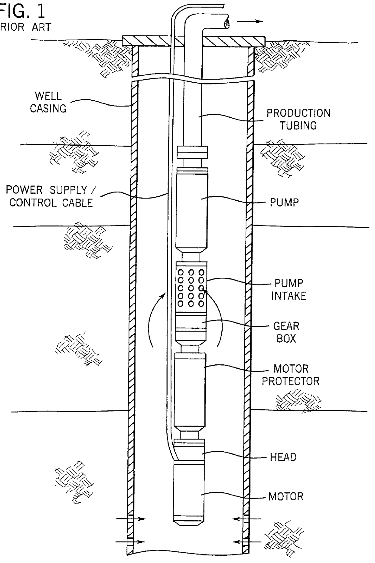
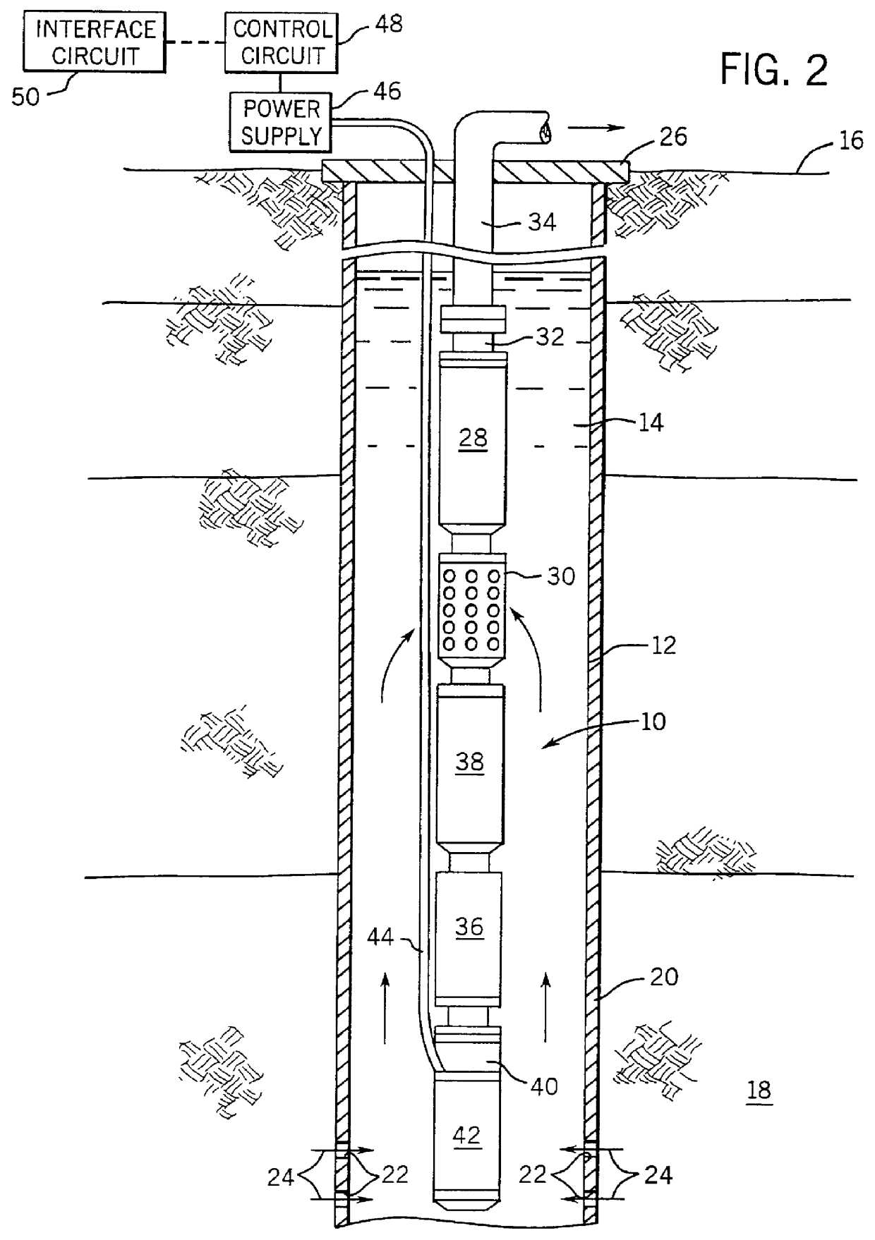
Turning now to the Figures, and referring first to FIG. 1, a pumping system is illustrated for raising fluids from a well in accordance with a known prior art technique. The pumping system consists of progressive cavity pump having a lower inlet and an upper outlet coupled to production tubing. The production tubing extends from the pump to a location above the earth's surface for discharging fluids displaced by the pump. The pump is driven by a motor and an intermediate gear box positioned in-line between the motor and the pump. It should be noted that in practice the gear box is typically much longer than illustrated diagrammatically in FIG. 1, adding significantly to the overall mass and length of the system. The motor is coupled to a power supply and control cable which extends from the motor head to control circuitry (not shown) above the earth's surface.

In a typical installation, the electric motor is a conventional polyphase induction motor or similar machine, coupled to thre...


PUM


Abstract

A submergible pumping unit for raising viscous fluids from a well is driven by an electronic drive and control system, a first portion of which is located above the well, and a second portion of which is coupled to the submergible pumping unit. The drive and control system includes a power supply circuit located above the well for converting AC power from a source to DC power having current and voltage levels. The DC power is transmitted to the pumping unit via a two-conductor DC bus cable. The pumping unit includes a switching circuit which receives the DC power for driving a submergible motor, such as a permanent magnet brushless motor. The speed of the motor, and of a pump coupled thereto, is proportional to the voltage of the DC power applied to the pumping unit. The pump is preferably a progressive cavity pump, and the drive and control circuitry provides sufficient torque to start the pump from a static condition. A control circuit is provided for transmitting configuration and desired flow rate and speed data to the power supply.

Description

1. Field Of The InventionThe present invention relates generally to the field of submergible pumping systems for producing fluids from wells, particularly petroleum production wells. More particularly, the invention relates to a novel technique for driving and controlling a submergible pumping system at a range of speeds, thereby permitting flow rates from the pumping system to be varied. The system is particularly well suited for driving pumping systems including progressive cavity pumps and similar devices having relatively high starting and low speed torque requirements.2. Description Of The Related ArtA variety of systems are known for producing viscous fluids from petroleum production wells and the like. Where the well formations provide sufficient pressure to raise wellbore fluids to the earth's surface without the aid of pumps, the well may be exploited directly, such as by appropriately equipping the wellhead with valving, transfer conduits, and so forth. However, in many pr...

Claims


Application Information

Patent Timeline
IPC IPC(8): F04C13/00F04B47/06F04B47/00F04C14/08
CPCF04B47/06F04C14/08F04C2/1071F04C13/008F04B2203/0202F04B2203/0209
Inventor BREIT, STEPHEN M.
Owner CAMCO INT
Why Eureka
Try Eureka