Coextrusion of liquid crystal polymers and thermoplastic polymers

a liquid crystal polymer and thermoplastic technology, applied in the field of thermoplastic polymer coextrusion, can solve the problems of mechanical anisotropy, inability to blow and draw after extrusion, and inability to meet the requirements of application,

Inactive Publication Date: 2000-04-04
SUPEREX POLYMER
View PDF8 Cites 14 Cited by
  • Summary
  • Abstract
  • Description
  • Claims
  • Application Information

AI Technical Summary

Problems solved by technology

Liquid crystal polymer films have desirable qualities in a number of applications, but significant drawbacks related to their mechanical anisotropy.
However, previously the mechanical properties of liquid crystal polymer films have been inadequate for these applications.
They cannot be blown and drawn after extrusion as coil polymers can, since they become too highly oriented in the die.
They are too weak in the non-orientation directions to be stretched after extrusion, even while in semi-flowable form.
However, the present inventors have observed a problem with this process which was not previously understood.
As best understood, liquid crystal polymer films have this curling problem because they are fibrillar, i.e., they comprise relatively straight molecules.
But the combination of shearing and stretching is much more critical and difficult to optimize with liquid crystal polymer extrudates, since they readily become hi...

Method used


Image

  • Coextrusion of liquid crystal polymers and thermoplastic polymers
  • Coextrusion of liquid crystal polymers and thermoplastic polymers
  • Coextrusion of liquid crystal polymers and thermoplastic polymers

Examples


first embodiment

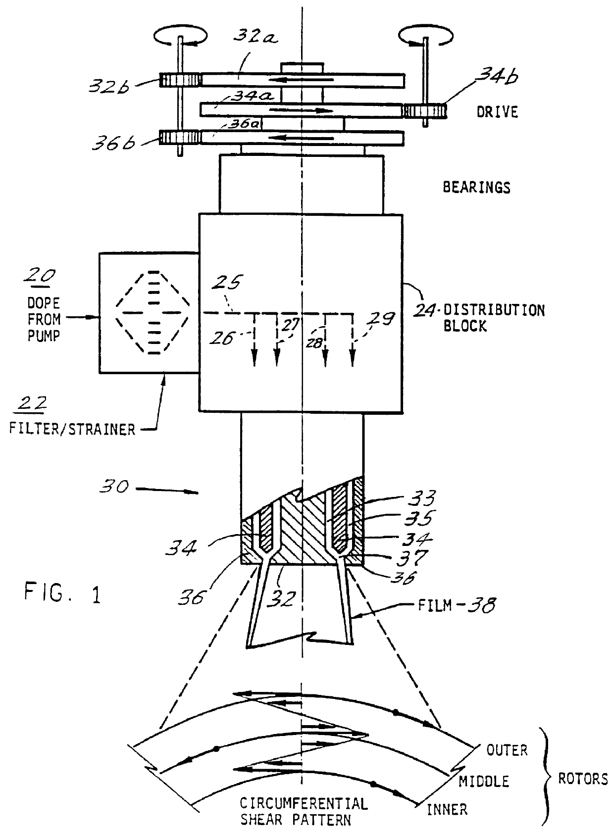
FIGS. 1 and 4-6 disclose a first method and a first apparatus for carrying out the invention. FIG. 4 is a schematic diagram, partly in cross-section, of a die that is particularly adapted to carry out the process of this invention. A liquid crystal polymer is plasticated by melting or solvating, then introduced at an inlet 51a. The LCP passes through distribution channel 51a and secondary distribution channels 51b and 51c. The channels 51a, 51b and 51c and 52a and 52b comprise a plurality of individual distribution channels, for receiving a plurality of respective types of polymers, and passing them to the respective channels 51a, 51b, and 51c and 52a and 52b.

A die assembly generally designated 30 comprises three tubular rotors, an inner tubular rotor 32, a middle tubular rotor 34, and an outer tubular rotor 36. A cylindrical inner space or annulus 33 is defined between the rotors 32 and 34. Similarly, an outer annulus 35 is defined between the rotors 34 and 36.

After passing through...

second embodiment

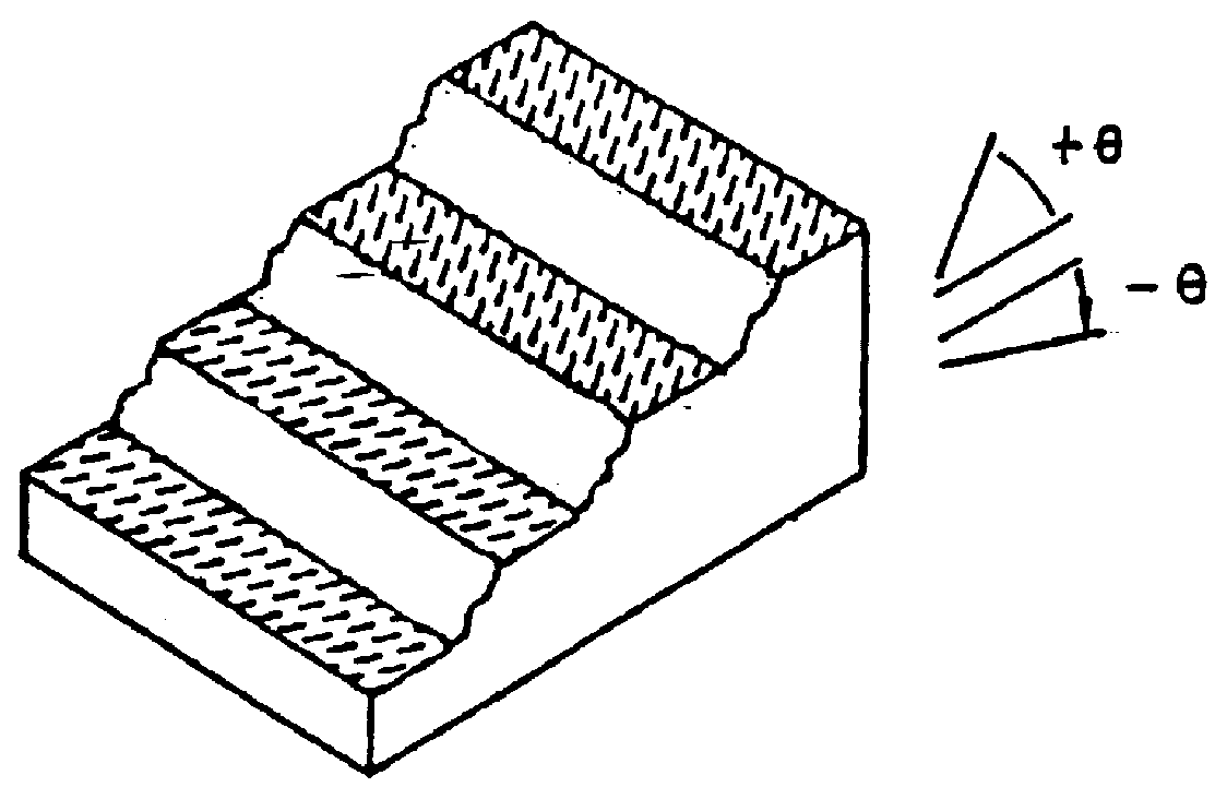
According to another aspect of the invention, the advantageous type of shear pattern similar to that shown in FIG. 1 can be obtained by another method. A conventional extrusion die which has two counter-rotating mandrels is known to produce a balanced biaxial film of a liquid crystal or a thermoplastic polymer or a blend thereof, with a structure such as shown in FIG. 2B. We have discovered that conventional film-layering and film adhesion apparatus and methods can be used to combine two such layers and thereby obtain a combined film having the shear pattern of FIG. 2B.

third embodiment

FIGS. 7-8 illustrate another method and apparatus embodying the invention. FIG. 7 shows a tri-axial (three-annulus) die which is a modification of the embodiments shown in FIGS. 1 and 4-6. Only the portions of this embodiment which differ from those in the first embodiment will be discussed, to eliminate redundant explanation.

In this embodiment, the inner rotor 32 and the outer rotor 36 are driven by the corresponding gearing 32a, 32b, 36a, 36b in opposite directions. A non-rotating member 34' is disposed between the inner and the outer rotors in a position corresponding to that of the middle rotor 34 in FIG. 1. A coaxial annular passage is formed through the non-rotating member 34'. The orientation of the film produced by this die is shown at the bottom of FIG. 7 and also in FIG. 8. A substantial central core layer of the film, which may constitute about 90% of its thickness, is oriented in the machine direction. The polymer material supplied to the inner annulus 33 and outer annul...


PUM

PropertyMeasurementUnit
Thermotropismaaaaaaaaaa
Molecular rotationaaaaaaaaaa
Molecular orientation enthalpyaaaaaaaaaa

Abstract

A flat and nearly mechanically isotropic polymer film or sheet, or a tube, can be formed by laminating two or more films, preferably by coextrusion of a liquid crystal polymer film and a thermoplastic polymer film. A liquid crystal polymer layer may be combined with one or more thermoplastic polymer layer in various arrangements. The liquid crystal, and possibly the thermoplastic as well, may have a controlled molecular orientation. The film may be formed by passing a polymer through a set of two or three tubular rotors which are concentric and have facing surfaces which define inner and outer annular polymer flow channels.

Description

1. Field of the InventionThe invention relates to methods and apparatus for forming polymer film, sheet or tube comprising a mechanically isotropic liquid crystal polymer (LCP) and a thermoplastic polymer (TP). It relates more particularly to forming a film which inherently maintains its shape and has a more uniform coefficient of thermal expansion than has been obtainable previously.The invention also relates to methods and apparatus for forming a coextruded polymer structure comprising at least one LCP layer and at least one TP layer, at least the LCP layer having a controlled molecular orientation.2. Description of Related ArtThe invention relates in general to the formation of multiaxially oriented films from high-molecular-weight liquid crystalline thermotropic or lyotropic polymers (homopolymers, copolymers, and the like), under processing conditions whereby the films have a controlled molecular orientation. These polymers generally fall into two classes, those that are modifi...

Claims


Application Information

Patent Timeline
IPC IPC(8): B29C47/06B29C55/00B29C47/28B29C47/20B29C47/24B29C48/10B29C48/33B29C48/34
CPCB29C47/0023B29C47/065B29C47/24B29C47/268B29C47/28B29C55/00B29C47/0026Y10T428/10B29K2105/0079B29C47/26B29C48/09B29C48/10B29C48/21B29C48/33B29C48/335B29C48/338B29C48/34C09K2323/00
Inventor HARVEY, ANDREW C.LUSIGNEA, RICHARD W.RUBIN, LESLIE S.
Owner SUPEREX POLYMER
Why Eureka
Try Eureka