Clock generator and clock generating method capable of varying clock frequency without increasing the number of delay elements

a clock generator and clock generating technology, applied in the direction of pulse generator, pulse manipulation, pulse technique, etc., can solve the problems of long time to re-operate, difficult control at a low voltage, long time, etc., and achieve the effect of reducing the frequency (multiplication number) of the output clock signal

Inactive Publication Date: 2000-04-11
RENESAS ELECTRONICS CORP
View PDF3 Cites 72 Cited by
  • Summary
  • Abstract
  • Description
  • Claims
  • Application Information

AI Technical Summary

Benefits of technology

The present invention is implemented to solve the foregoing problems. It is therefore an object of the present invention to provide a clock generator and a cl

Problems solved by technology

The analog PLL, however, has problems of being not easy to control at a low voltage, susceptible to noise, and requiring a rather long time to re-operate once it has suspended its oscillation in response to the halt of the input clock signal, because it takes a long time (lock time) until its operation becomes stable.
Since the delay elements and the decoder occupy a rather

Method used


Image

  • Clock generator and clock generating method capable of varying clock frequency without increasing the number of delay elements
  • Clock generator and clock generating method capable of varying clock frequency without increasing the number of delay elements
  • Clock generator and clock generating method capable of varying clock frequency without increasing the number of delay elements

Examples


embodiment 1

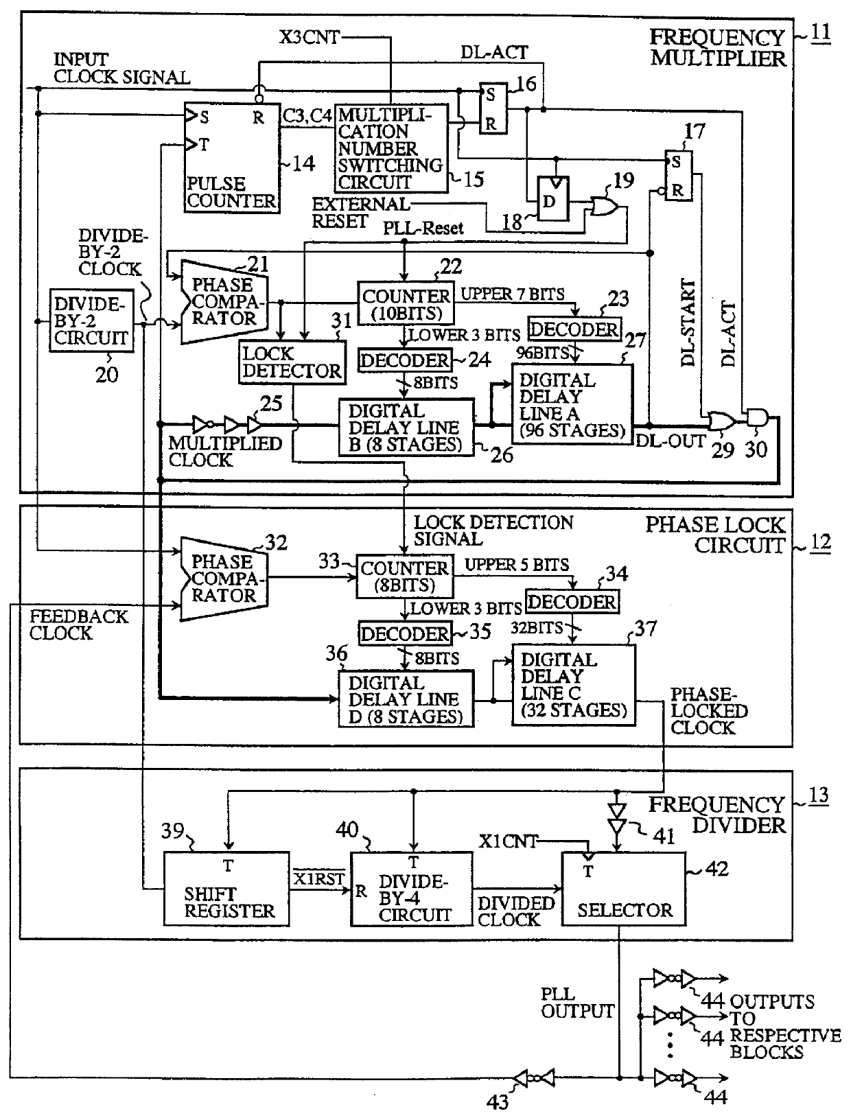
FIG. 1 is a block diagram showing an embodiment 1 of a clock generator in accordance with the present invention. In FIG. 1, the reference numeral 11 designates a frequency multiplier for generating a frequency multiplied clock signal by multiplying the frequency of an input clock signal; 12 designates a phase lock circuit for synchronizing the phase of a feedback clock signal (corresponding to a frequency divided clock signal) with that of the input clock signal by delaying the phase of the frequency multiplied clock signal generated by the frequency multiplier 11; and 13 designates a frequency divider for detecting, from among the phase-locked clock signal output from the phase lock circuit 12, a phase-locked clock pulse immediately previous to the falling edge of a pulse of the input clock signal, and for frequency dividing the phase-locked clock signal with reference to the detection point, thereby supplying the phase lock circuit 12 with the frequency divided signal or phase-loc...

embodiment 2

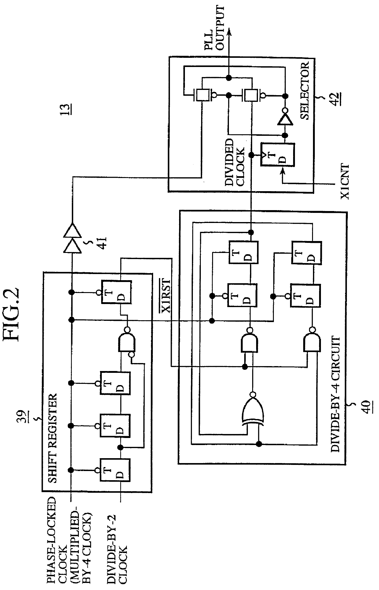
Although the phase-locked clock signal is divided by four to generate the PLL output with the same period as that of the input clock signal in the foregoing embodiment 1, this is not essential. For example, the frequency multiplied clock signal multiplied by n may be generated and be divided by m to produce n / m PLL output, where n and m are natural numbers.

Replacing the divide-by-4 circuit 40 with a divide-by-m circuit can limit the length of the digital delay lines 36 and 37 in the phase lock circuit 12 within 1 / m of the period of the PLL output.


PUM


Abstract

A clock generator including a frequency multiplier, a phase lock circuit and a frequency divider. The frequency multiplier generates a frequency multiplied clock by multiplying the frequency of an input clock. The phase lock circuit detects a phase difference between the input clock and a frequency divided clock, and generates, by delaying the frequency multiplied clock by an amount corresponding to the phase difference, a phase-locked clock with its phase locked with the input clock. The frequency divider detects in every fixed cycle a particular pulse of the phase-locked clock, and generates the frequency divided clock by dividing the phase-locked clock with reference to the particular pulse of the phase-locked clock. In particular, the frequency divider detects the particular pulse immediately previous to a falling edge of the input clock. This can reduce the phase difference between the input clock and the phase-locked clock, and hence to solve a problem of a conventional clock generator in that a delay time of a digital delay line in a phase lock circuit must be lengthened with a reduction in the multiplication number of the frequency multiplied clock, which requires a greater number of delay elements because of a large occupying area of the delay elements and a decoder, thereby increasing the circuit scale and cost of a chip to reduce the multiplication number of the frequency multiplied clock.

Description

BACKGROUND OF THE INVENTION1. Field of the InventionThe present invention relates to a clock generator and a clock generating method for generating a frequency divided clock signal with the same period as an input clock signal or frequency multiplied clock signal.2. Description of Related ArtFIG. 10 shows a configuration of a conventional clock generator disclosed in Technical report of the Institute of electronics, information and communication engineers of Japan, pp. 29-36, Vol. 97, No. 106, published June, 1997, which is incorporated here by reference. In FIG. 10, the reference numeral 1 designates a frequency multiplier for generating a frequency multiplied clock signal by frequency multiplying an input clock signal; 2 designates a ring oscillator consisting of a digital delay line 3 for delaying the frequency multiplied clock signal; 3 designates the digital delay line of the ring oscillator 2; 4 designates a counter for setting a delay time of the digital delay line 3; 5 desig...

Claims


Application Information

Patent Timeline
IPC IPC(8): H03L7/06H03K3/86H03K3/027H03L7/08H03K3/00H03L7/16H03L7/181
CPCH03K3/027H03K3/86H03L7/181H03L7/08H03L7/06H03L7/0995H03L7/18H03L7/0816H03L7/0891H03L7/0805H03K5/133H03L7/0996H03L7/0814H03K5/00006H03K3/0315H04L7/00
Inventor SHIMIZU, KAZUYOSHIISHIMI, KOUICHISAWAI, KATSUNORI
Owner RENESAS ELECTRONICS CORP
Why Eureka
Try Eureka