Pivotable and sealable cap assembly for opening in a large container

a container and cap assembly technology, applied in the direction of closure lids, tank vehicles, items transportation vehicles, etc., can solve the problems of time-consuming and rather dangerous work phases

Inactive Publication Date: 2000-04-25
MORCH LEO
View PDF13 Cites 83 Cited by
  • Summary
  • Abstract
  • Description
  • Claims
  • Application Information

AI Technical Summary

Problems solved by technology

As is evident, these phases of work are very time-consuming and rather dangerous to the driver who has to climb the top of the tank lorry twice during the filling process and in a substantial height above the ground make a number of manual operations, even in unpleasant weather such as rain, sleet or snow.

Method used


Image

  • Pivotable and sealable cap assembly for opening in a large container
  • Pivotable and sealable cap assembly for opening in a large container
  • Pivotable and sealable cap assembly for opening in a large container

Examples


Embodiment Construction

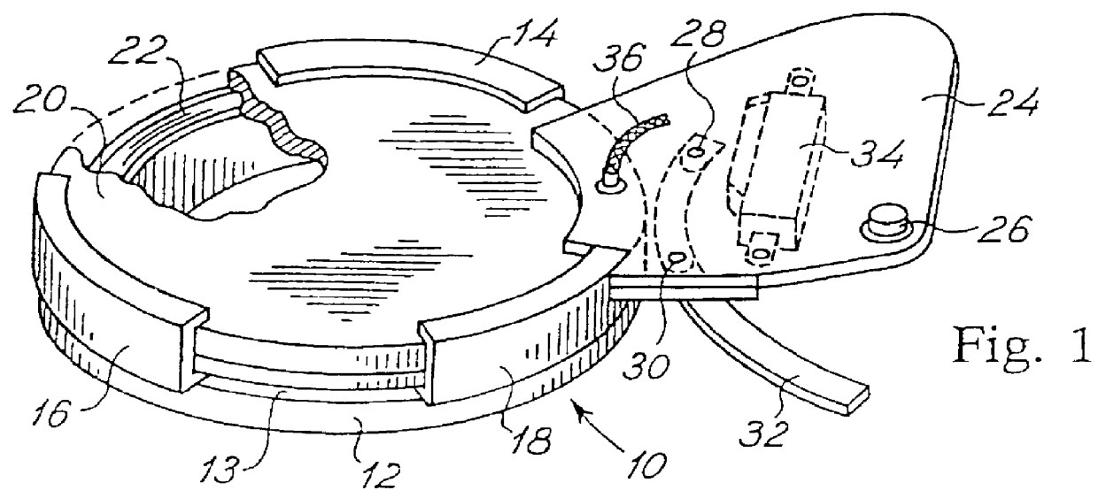
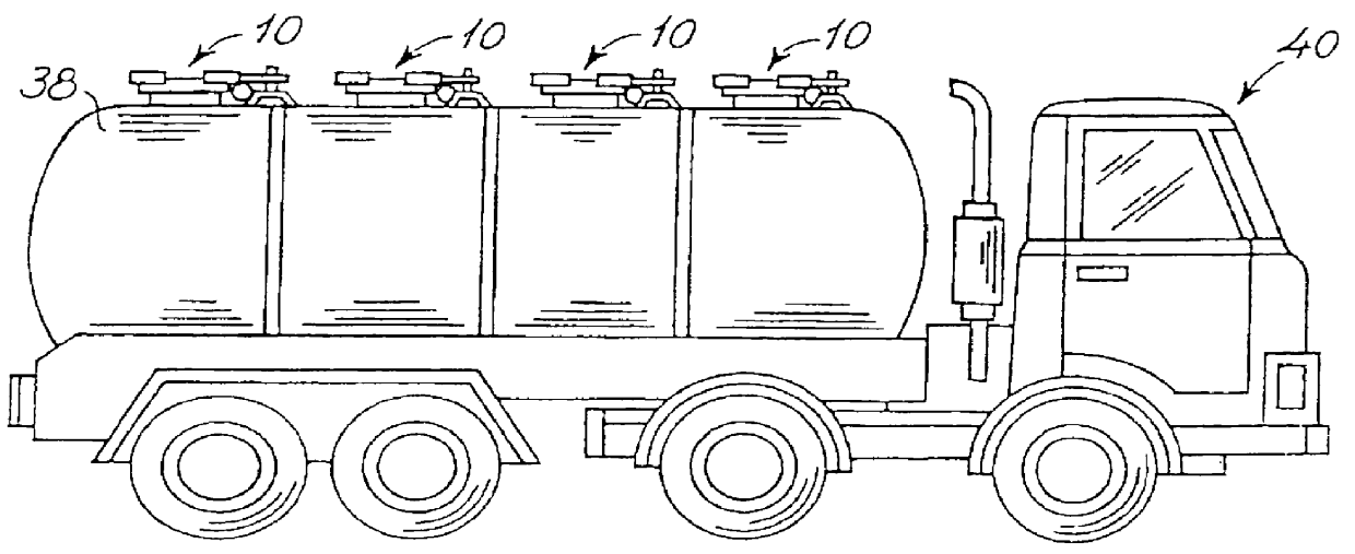
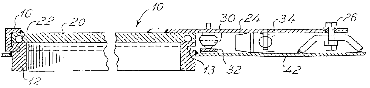
FIG. 1 is a schematic and perspective view of the first and presently preferred embodiment of a cover assembly including a circumferential skirt and a cap unit for covering and closing an upper, outer end of the skirt which is positioned around an aperture in a top wall of a large container or pressure tank, especially a tank lorry container for transportation of fluid or particulate material such as chemicals, powders, feedstuff, etc. During transportation the materials to be transported is kept at a pressure above atmospheric of typically 0.5-8, such as 0.6 bar. In accordance with the present invention the cap unit is, as will be described in further details below, produced as a revolvable cap unit. In FIG. 1 the cap unit according to the present invention is designated the reference numeral 10 and is mounted on an upwardly extending circular cylindrical skirt 12, along which a circular section of approx. 60.degree. is covered by clamps 14,16 and 18 having equal angle spacing and ...


PUM


Abstract

A cap unit (10) for a container (38) has a cap (20) and an annular skirt (12). The skirt (12) is mounted in the container (38) defining an aperture, the cap (20) being movable between a first position and a second position. In the first position the cap (20) covers the aperture and seals it, and in the second position the cap uncovers the aperture, the cap (20) being journalled pivotably around an axis (26) perpendicular to the plan defined by the aperture and placed outside the aperture so that the cap may swing between the first position and the second position. Furthermore, the cap (20) and the skirt (12) have respective claw-formed catching means (14, 16, 18) which are adapted to fix the cap (20) in relation to the skirt (12) and allow the cap (20) to swing from a first to a second position. The cap unit (10) has driving means (34) for production of swinging of the cap (20) and the cap unit (10) has an inflatable sealing ring (22) mounted in the cap (20) for sealing against the upper surface of the skirt (12) when the cap (20) is in its first position, or alternatively mounted in the skirt (12) for sealing against the opposite surface of the cap (20).

Description

1. FIELD OF THE INVENTIONThe present invention relates to a cap unit for a container, especially a container on a tank lorry or similar means of transport and having a cap and a circumferential skirt, in which container the skirt is mounted defining an aperture in the container and which cap is movable between a first position and a second position in which first position the cap covers the aperture and seals it and in which second position the cap at least partly uncovers the aperture, the cap being revolvably journalled around an axis extending perpendicularly to the plane defined by the aperture and being located outside the aperture so that the cap is able to swing in a plan parallel with the plane defined by the aperture between the first position and the second position, and the cap and the skirt having respective claw-shaped catching means which are arranged so as to maintain the cap longitudinally in relation to the skirt and at the same time allow the cap to swing from the ...

Claims


Application Information

Patent Timeline
Patent Type & Authority Patents(United States)
IPC IPC(8): B60P3/22F16J13/22F16J13/00
CPCB60P3/224F16J13/22B60P3/226
Inventor MORCH, LEO
Owner MORCH LEO
Why Eureka
Try Eureka