J hook-type hook strip for a mechanical fastener

a technology of mechanical fasteners and hook strips, which is applied in the direction of snap fasteners, mechanical vibration separation, electric/magnetic/electromagnetic heating, etc., can solve the problems of difficult to impregnate the polymer in the supporting fabric, limited methods,

Inactive Publication Date: 2000-04-25
3M CO
View PDF41 Cites 216 Cited by
  • Summary
  • Abstract
  • Description
  • Claims
  • Application Information

AI Technical Summary

Benefits of technology

The invention overcomes the above-identified limitations in the field by providing a simple method of making a hook strip having J-shaped hooks that can be used as a mechanical fastener. In a preferred embodiment, the method includes using a pre-existing substrate of material formed as an array of upstanding stems of thermoplastic material on a backing, the stems having tips at the ends opposite the end attached to the backing. The stem generally taper from base to tip and is preferably symmetrical along its length, e.g., circular or polygonal. In addition, a heat source adapted for

Problems solved by technology

However, this method would likewise be limited to shapes that must taper inward except in this case, from one outer face to an opposin

Method used


Image

  • J hook-type hook strip for a mechanical fastener
  • J hook-type hook strip for a mechanical fastener
  • J hook-type hook strip for a mechanical fastener

Examples


example 1

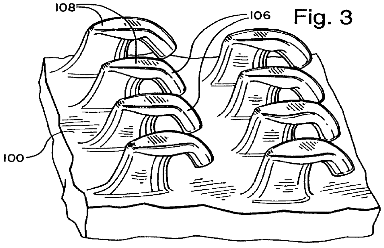
A roll having a plurality of J-shaped hooks 106, such as those shown in FIG. 3, was made under the conditions of Table I with the resulting dimensions of Table II below. In Table I, Relative Speed means the speed of the heated roll relative to the substrate line speed (so in Table 1, -70 percent means the heated roll is moving in an opposite direction to the substrate at a speed of 14 feet / minute).

TABLE II

The tests used independent hook strips 100 of a 2.54 centimeter (cm) by 10.16 cm size. The tests included a shear strength test using ASTM D-5169 and a 135 degree peel test conducted in the machine direction (MD) (for best hook engagement) and in the cross web direction (CD) (for nominal hook engagement). The peel test consisted of a 135 degree peel from a test patch of XML-4069 loop (commercially available from Minnesota Mining & Manufacturing Company) at a peel rate of 30.5 cm per minute. The hook samples were rolled down onto the loop using five passes of a 2.04 kilogram (4.5 po...

examples 2 through 17

In these examples, a device as shown in FIG. 5 was employed where the top heated calender roll 172 was heated with oil; the bottom calender roll 170 was chilled with water. Both rolls were chrome plated and approximately 10 inches in diameter. The bottom chilled calender roll was fixed and 3 inch diameter pistons were used to position the heated calender roll. The gap between the heated calender roll and the chilled calender roll was set with a screw and stop set up. For the experiments described below, a pressure of 40 psi in the pistons was sufficient to prevent the heated roll from floating (opening the gap) when the precursor material was calendered.

The speed of the heated roll (s2) could be set independently of the speed of the chilled roll (s1). The overspeed is the difference between s1 and s2. For example, a 110 percent overspeed means that the heated roll was turning 10 percent faster than the chilled roll; a -70 percent overspeed means that the heated roll was turning back...

examples 18 through 33

For Examples 18 through 33 the gap width was changed to 0.5 mm (0.019 in.). Otherwise the examples were run on the equipment described for Examples 2 through 17 with the conditions set forth in these examples and in Table VII below.

The dimensions of the Examples 18 through 33 hook materials were then measured as were Examples 2 through 17 and as set forth in Table VIII. The reported measured values were the average of six different hooks.

These examples were then tested for peel performance as were Examples 18 through 33. The same trends were noticed.


PUM

PropertyMeasurementUnit
Speedaaaaaaaaaa
Speedaaaaaaaaaa
Temperatureaaaaaaaaaa

Abstract

A method of making a hook strip having J-shaped hooks that can be used as a mechanical fastener. The method includes using an initial substrate of material formed as an array of upstanding precursor stems having distal tips at their ends opposite a backing. In addition, a heat source adapted for heating and a mechanism for deforming stem tips is provided. The substrate is positioned relative to the heat source such that a portion of the upstanding stems on the array is heated. Subsequently, the substrate is moved to a position relative to the mechanism for deforming to create a hook strip of J-shaped hooks from the heated portion of the upstanding stems. In addition, an article of manufacture, made in accordance with the method, is provided which includes a hook portion of a hook-and-loop type of mechanical fastener.

Description

The invention relates generally to mechanical fasteners such as hook-and-loop fasteners. More particularly, the invention relates to J hook-type hook strips such as can releasably close a garment, e.g., a disposable garment such as a diaper or a hospital gown when attached to a suitable loop material.Hook-and-loop fasteners are widely used as garment fasteners. Commercial examples of these fasteners include those marketed under the VELCRO brand by Velcro USA Incorporated and under the SCOTCHMATE brand by Minnesota Mining and Manufacturing Company, St. Paul, Minn., which fasteners are made by a variety of methods. Early versions of the hook materials still available today are taught in U.S. Pat. Nos. 2,717,437 and 3,009,235 (both by DeMestral), where a hook strip is made from specific warps of upstanding nylon loop pile. One leg of each loop is cut to leave an open-ended J-shaped hook, which is available to act as a fastening element.U.S. Pat. No. 3,594,865 (Erb) describes an injecti...

Claims


Application Information

Patent Timeline
IPC IPC(8): A44B18/00B29C43/22
CPCA44B18/0049A44B18/0061B29C43/222B29C43/46Y10T24/2792B29C2043/461B29L2031/729
Inventor MILLER, PHILIPMELBYE, WILLIAM L.
Owner 3M CO
Why Eureka
Try Eureka