Fluid delivery apparatus

a technology of flue gas and delivery apparatus, which is applied in the direction of water mains, gas/liquid distribution and storage, structural/machine measurement, etc., can solve the problems of material handling, and real hazards to operators, and the failure of one of the valves can remain undetected

Inactive Publication Date: 2000-05-02
PLANER PROD LTD
View PDF3 Cites 119 Cited by
  • Summary
  • Abstract
  • Description
  • Claims
  • Application Information

AI Technical Summary

Problems solved by technology

It can easily be seen that the consequences of failure of such a valve may be serious; though relatively rare, such failures, in particular failure to close, provide real hazards to operators, as well as to materials being handled.
However, failure of one of the valves can remain undetected until the other valve fails, because until this happens the failure of the first valve is masked by the one still operating.
We have found, surprisingly, that if both valves are closed simultaneously, or if the upstream valve is closed before the downstream one, a back pressure is set up in the flow line which is undesirable.
In this connection, however well the flow line is lagged, the thermal insulation of the latter will never be perfect in practice.

Method used


Image

  • Fluid delivery apparatus
  • Fluid delivery apparatus

Examples


Embodiment Construction

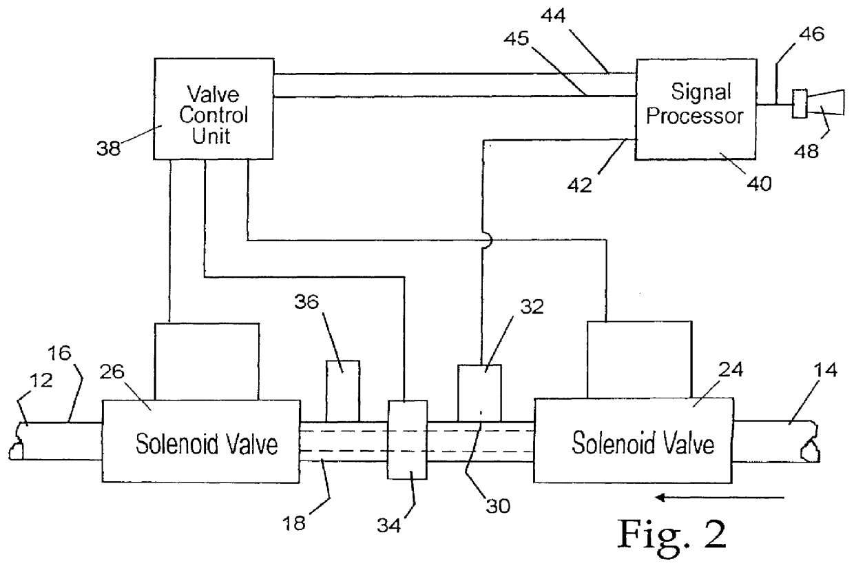
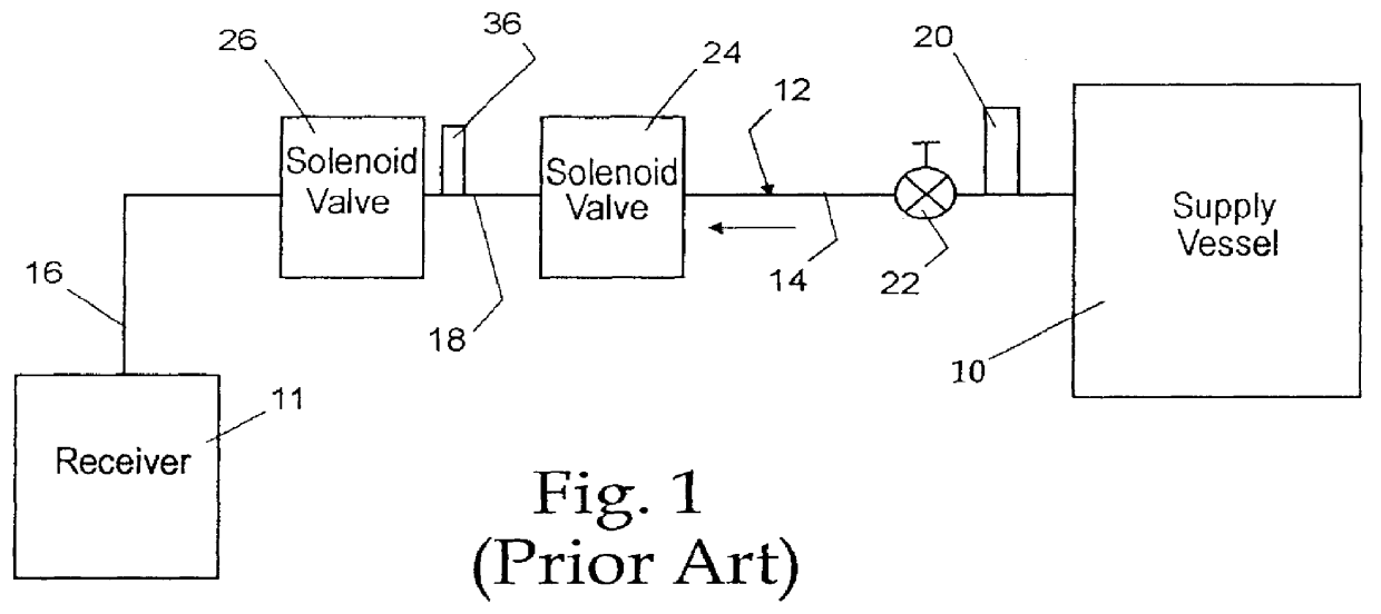
In the prior art arrangement shown in FIG. 1, a fluid is delivered from a supply vessel 10 to a receiver 11 through a flow line 12 comprising an upstream section 14, a downstream section 16, and an intermediate section 18 joining the section 14 and 16 and containing a safety valve 36. The upstream section 14 contains a safety valve 20 associated with the supply vessel, and a manually operated main shut-off valve 22. Two solenoid valves 24 and 26 are fitted in the flow line 12 at the upstream and downstream end of intermediate section 18, respectively. The valves 24 and 26 are thus in series, so that, although failure of one of these valves to close when it should will not prevent the delivery of fluid from being stopped by the other one so long as the latter is still working correctly, the failure of one valve may not be noticed until the second one also fails, as discussed above.

The apparatus, of which only one part is shown in FIG. 2, is the same as that in FIG. 1 except in the re...


PUM


Abstract

A line, especially for delivery of liquefied gas at ambient temperature, has two solenoid valves connected in series with an intermediate section of the line between them. In normal operation when both valves are closed, the isolated intermediate section contains liquid which absorbs heat from the atmosphere and/or from a heater, and the resulting increase in pressure is detected by a pressure sensor. If either valve fails to close fully to shut off flow, the intermediate section is not then isolated, so the absence of a signal from the sensor (the valves being set to close fully) indicates that at least one of them has not properly closed, and an alarm is given.

Description

1. Field of the InventionThis invention relates to fluid delivery apparatus including a flow line for delivery of fluid through the flow line from a source to an outlet, with flow control means, for controlling the delivery of the fluid, being connected in the flow line.The fluid may be in the form of a liquid, gas, or vapor, or a mixture of any one or more of these. However, the invention is especially applicable to use with liquids, and, among these, those liquids which have a boiling point below ambient temperatures.2. Discussion of the Prior ArtLiquefied gas is widely used in research in industry and in medicine, including for example liquid oxygen, nitrogen, carbon dioxide, helium, or air. These cooled liquids are usually dispensed as needed from large vessels into smaller containers or other apparatus, through a flow line in the form of a hose or pipe, often with one or more in-line taps or valves to control the flow. The operation of such taps or valves may be automatic, that...

Claims


Application Information

Patent Timeline
Patent Type & Authority Patents(United States)
IPC IPC(8): G01M3/28
CPCG01M3/2876Y10T137/8158Y10T137/8242Y10T137/8326
Inventor LAKRA, PAUL
Owner PLANER PROD LTD
Why Eureka
Try Eureka