

Tree running tool with emergency release
a running tool and tree technology, applied in the direction of drilling machines and methods, underwater drilling, drilling machine parts, etc., can solve the problems of low preload, low preload, and the connection to unlatch independent of the hydraulic actuation system, and achieve the effect of very efficient and fast, and time-consuming
- Summary
- Abstract
- Description
- Claims
- Application Information
AI Technical Summary
Benefits of technology
Problems solved by technology
Method used
Image

Examples
Embodiment Construction
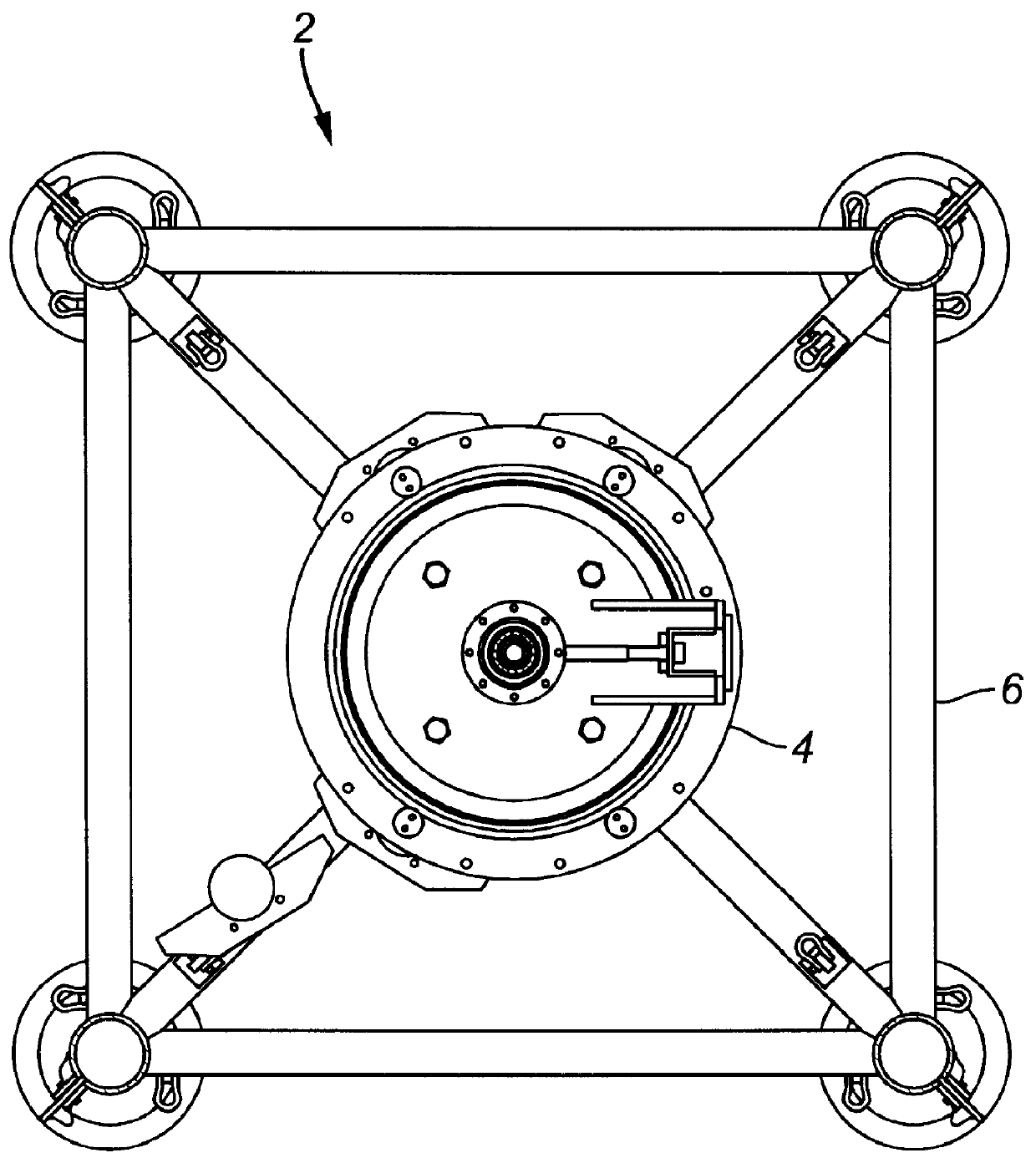
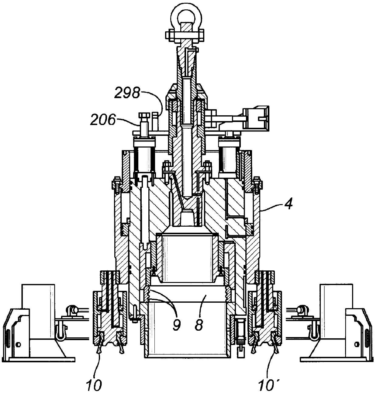
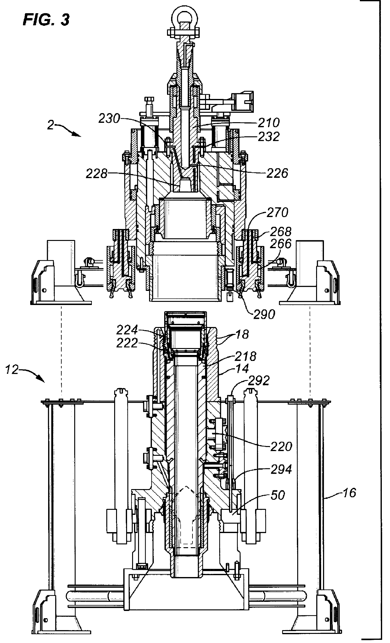
In accordance with certain preferred aspects of the present invention, there is provided tree running tool 2 with a mechanical mechanism for unlatching the tree running tool from a side valve tree. The tree running tool is formed from a tool body 4, a stem 210, a telescoping element 68, a retractable spacer 62, a means 60 for moving the spacer, and a means 66 for attaching the telescoping element to a lift device.
The tool body has an upper end, a lower end, and a longitudinal axis.
The stem is fixedly attached to the upper end of the tool body and extends axially therefrom. The stem has a lower end attached to the tool body and a generally annular flange at a position spaced apart from the tool body.
The telescoping element is positioned alongside the stem. The telescoping element has a generally annular flange at a position between the generally annular flange of the stem and the tool body.
The retractable spacer is movable from an engaged position between the generally annular flange...
PUM
 Abstract
Description
Claims
Application Information