
Cleaning device for a window/headlamp cover of a motor vehicle

Inactive Publication Date: 2000-05-16
CONTINENTAL AUTOMOTIVE GMBH
View PDF9 Cites 45 Cited by
  • Summary
  • Abstract
  • Description
  • Claims
  • Application Information

AI Technical Summary

Benefits of technology

This arrangement enables the washer nozzles of the joint component to be configured as individual washer nozzles independently of one another to match intended spraying regions and spraying pressures, with the result that even asymmetrical window / headlamp covers are cleaned completely through addition of the spraying areas of appropriately designed washer nozzles. In addition, this can easily avoid the situation where washing fluid falls alongside the window / headlamp cover. Unlike in the known cleaning device, frictional losses within the washer nozzles of the cleaning device according to the invention result in only a slightly changed spraying region on the window / headlamp cover. The invention enables outlay on construction to be particularly low even if there are a multiplicity of washer nozzles in the joint component. The cleaning device according to the invention is therefore also suitable for windshields and rear windows of motor vehicles or for window / headlamp covers in which afterwiping is carried out by a wiper after the washing fluid has been sprayed on.
The cleaning device according to the invention enables a window / headlamp cover of large surface area to be cleaned without afterwiping if the joint component has a partition in a central region, and a respective washer nozzle designed as a fluidic chip is arranged on each side of the partition. Washer nozzles designed as a fluidic chip produce a washing fluid jet of particularly small cross section, which swings to and fro cyclically. Because the washing fluid jet swings to and fro, for example, a strip-shaped region of the window / headlamp cover can be wetted with washing fluid. The washing fluid jet in this case has a very high pressure and so dirt adhering to the window / headlamp cover is washed away. These washer nozzles have oval or strip-shaped spraying regions which can easily be added to form a large spraying region.
The supply of the washer nozzles with washing fluid is configured in a particularly simple manner if the partition has a recess for the overflow of washing fluid from one washer nozzle to the other washer nozzle.
According to another advantageous feature of the invention, the washer nozzles can be manufactured particularly cost-effectively if walls of a shaft which supports the joint component each form a boundary of a space for fluid in the washer nozzles. Particularly when the washer nozzles are designed as fluidic nozzles, this design results in a very simple construction since, to produce the washing fluid jet which swings to and fro, fluidic nozzles generally have a large space for fluid with block-shaped inserts. A component having two washer nozzles can thereby be produced, for example, in an axially releasable injection mold or sintering mold.
According to another advantageous development of the invention, the component which has the washer nozzles can be installed in a particularly simple manner if the joint component of the washer nozzles and the shaft are each of wedge-shaped design. This design enables the washer nozzles to be aligned in the shaft automatically during installation.
According to another advantageous development of the invention, the installation of the component which has the washer nozzles requires particularly low outlay in terms of time if in the region of the partition the joint component has protruding pegs, and a nozzle stem which supports the component has latching elements which engage around the pegs. In addition, installation can be automated.

Problems solved by technology

The disadvantage of the known cleaning devices is that it is difficult to adapt the spraying region of the washer nozzle to the shape of the window / headlamp cover.
For example, frictional losses within the washer nozzle frequently lead to the spraying region becoming restricted and hence to the corner regions of the window / headlamp cover being inadequately cleaned.
Furthermore, during installation, the washer nozzle has to be aligned with respect to the window / headlamp cover in a complex procedure.
This results in the cleaning device being installed manually in a very cost-intensive manner.
The washing fluid jet in this case has a very high pressure and so dirt adhering to the window / headlamp cover is washed away.

Method used


Image

  • Cleaning device for a window/headlamp cover of a motor vehicle
  • Cleaning device for a window/headlamp cover of a motor vehicle
  • Cleaning device for a window/headlamp cover of a motor vehicle

Examples


Embodiment Construction

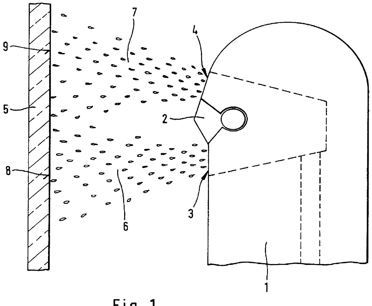
FIG. 1 shows a component 2 which is fastened in a nozzle stem 1 and has two washer nozzles 3, 4. The nozzle stem 1 is directed with the washer nozzles 3, 4 onto a window / headlamp cover 5. The window / headlamp cover 5 may be, for example, a lens cover of a motor vehicle headlamp or a motor vehicle windshield or rear window. The washer nozzles 3, 4 are designed as fluidic nozzles and in each case produce a washing fluid jet 6, 7 of particularly small cross section which swings to and fro cyclically perpendicularly with respect to the plane of projections. The washer nozzles 3, 4 thereby respectively produce strip-shaped spraying regions 8, 9 on the window / headlamp cover 5, which spraying regions complement one another to form a large spraying region. At the same time, a negative pressure is produced between the washing fluid jets 6, 7 and this leads to the trajectory of individual washing fluid drops being bent toward the other washing fluid jet 8, 9 in each case. This causes that regi...


PUM


Abstract

A cleaning device for a window / headlamp cover (5) of a motor vehicle has two washer nozzles (3, 4) which are manufactured as ajoint component (2) and in each case produce strip-shaped spraying regions (8, 9) on the window / headlamp cover (5). The spraying regions (8, 9) are arranged one above the other and thus complement one another. This means that a large region of the window / headlamp cover (5) is wetted with washing fluid without washing fluid falling alongside the window / headlamp cover (5).

Description

FIELD AND BACKGROUND OF THE INVENTIONThe invention relates to a cleaning device for a window / headlamp cover of a motor vehicle, having a washer nozzle which sprays washing fluid onto the window / headlamp cover.Cleaning devices of this type are frequently used, for example, for vehicle headlamp lens covers, and are known from practice. In these cases, as large a region of the window / headlamp cover as possible is sprayed with washing fluid by the washer nozzle. If the washer nozzle is designed appropriately, it is possible for the window / headlamp cover to be cleaned without afterwiping just by the washing fluid being sprayed on.The disadvantage of the known cleaning devices is that it is difficult to adapt the spraying region of the washer nozzle to the shape of the window / headlamp cover. For example, frictional losses within the washer nozzle frequently lead to the spraying region becoming restricted and hence to the corner regions of the window / headlamp cover being inadequately clean...

Claims


Application Information

Patent Timeline
IPC IPC(8): B05B1/14B60S1/46B60S1/52B05B1/10
CPCB60S1/52B05B1/14
Inventor HAHN, TORSTENNEUMANN, WILLI
Owner CONTINENTAL AUTOMOTIVE GMBH
Features
  • Generate Ideas
  • Intellectual Property
  • Life Sciences
  • Materials
  • Tech Scout
  • Unparalleled Data Quality
  • Higher Quality Content
  • 60% Fewer Hallucinations
Learn More