Magnetotherapeutic back massager and method of making same

a magnetic therapy and back massage technology, applied in the field of back massagers, can solve the problems of widening of the associated blood vessel and gently churning

Inactive Publication Date: 2000-05-23
NYUU MAGUNETEIKUSU
View PDF17 Cites 49 Cited by
  • Summary
  • Abstract
  • Description
  • Claims
  • Application Information

AI Technical Summary

Benefits of technology

It is an object of the present invention to provide a method by which a magnetotherapeutic back massager can be more easily constructed.
It is another object of the present invention to provide such a method that allows the easy application and association of the magnetotherapeutic magnets with the roller core of the magnetotherapeutic back massager.
It is an additional object of the present invention to provide a magnetotherapeutic back massager that does not inhibit the magnetic effect of incorporated magnets.

Problems solved by technology

When exposed and caused to so travel through a magnetic field, such ions and electrolytes may generate heat, causing the associated blood vessel to widen.
The mechanical motion of the rotation of such polar molecules might also cause heating and the like and would also stimulate, mix, or agitate the blood in a gentle manner, causing it to gently churn.
While devices facilitating back massage are known in the art, only a very few of these combine magnetotherapy with back massage.

Method used


Image

  • Magnetotherapeutic back massager and method of making same
  • Magnetotherapeutic back massager and method of making same
  • Magnetotherapeutic back massager and method of making same

Examples


Embodiment Construction

)

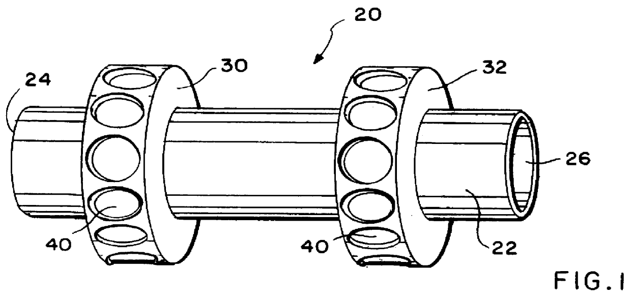
The present invention resides in a novel method by which a magnetotherapeutic back massager may be more efficiently and conveniently formed, constructed, and manufactured. By making the manufacturing process easier, more economical use of resources and more efficient manufacturing techniques can be implemented. Additionally, the inventive method used to form the magnetotherapeutic back massager relies upon generally magnetically-inert materials so that the magnetic fields present about the magnets used in the magnetotherapeutic back massager are not unduly limited or diminished. As shown in FIG. 1, a roller blank generally serves as a core for the magnetotherapeutic back massager constructed as a result of the present inventive method.

In FIG. 1, the roller blank 20 is preferably made of latex rubber or the like, but can be constructed of like materials that serve the back massaging purposes of the present invention. The roller blank 20 has a central cylindrical core 22 having open ...


PUM

PropertyMeasurementUnit
lengthaaaaaaaaaa
lengthaaaaaaaaaa
magneticaaaaaaaaaa

Abstract

A method for manufacturing a magnetotherapeutic back massager. A roller blank having a central cylindrical core circumscribed by a pair of spaced apart circular projections receives magnets in the circular projections to provide magnetic properties to the resultingly constructed magnetotherapeutic back massager. Preferably, the magnets are arranged so as to alternate polarity and a magnet-supporting strip holds the magnets together prior to and during the association of the magnets with the circular projections. The circular projections may have indentations or grooves to accommodate the magnets. Once the magnets have been associated with the circular projections, the magnets are more permanently attached by applying additional material to the circular projections so as to seal the magnets to the circular projections. The sealing material may be the same as that used to construct the roller blank, preferably latex rubber. Either prior to or after the sealing process, the magnet-supporting strip is removed from the magnets leaving them held in place by the circular projections of the roller blank. A cover, preferably bi-lobed and knobbed, is then applied to the now-magnetized roller blank. Roller bearings attached to the roller blank allow the central, bi-lobed massaging core to articulate rotatably with respect to the central spindle shaft. The central spindle shaft may have handles at opposite ends to facilitate manipulation of the resultingly-constructed magnetotherapeutic back massager.

Description

1. Field of the InventionThis invention relates to back massagers that roll upon a spindle shaft, and more particularly to a method of making a magnetotherapeutic back massager that uses magnets to invoke magnetotherapeutic response in the person being massaged.2. Description of the Related ArtMagnetotherapy uses magnetic fields to provide therapeutic and restorative treatment to limbs, organs, and other parts of the body. Generally, one means by which magnetotherapy may be achieved is by bringing a magnet or series of magnets into close proximity with the affected body part or organ of interest. As is known according to Faraday's Law of Magnetic Induction, as well as the Hall Effect, charged particles experience a force acting on them when they move through a magnetic field in a perpendicular direction. Since human blood is replete with ions and electrolytes, it has many charged particles which experience a force, including an aligning force, when moving through a magnetic field. W...

Claims


Application Information

Patent Timeline
Patent Type & Authority Patents(United States)
IPC IPC(8): A61H15/00B23P15/00
CPCA61H15/0092B23P15/00A61H2201/10Y10T29/49561Y10T29/49549A61N2/00
Inventor BOVE, THOMAS A.
Owner NYUU MAGUNETEIKUSU
Why Eureka
Try Eureka