Self-calibrating optical fiber pressure, strain and temperature sensors

a self-calibration, optical fiber technology, applied in the direction of force measurement by measuring optical property variation, instruments, heat measurement, etc., can solve the problems of limiting the accuracy of compensation of optical fiber sensors, imperfect light transmission through optical fibers, and reducing the accuracy of optical fiber sensors

Inactive Publication Date: 2000-05-30
VIRGINIA TECH INTPROP INC
View PDF1 Cites 77 Cited by
  • Summary
  • Abstract
  • Description
  • Claims
  • Application Information

AI Technical Summary

Problems solved by technology

Many of these applications require very precise measurement of a physical parameter and often at extremely inaccessible locations and/or where severe conditions exist.
However, transmission of light through optical fibers, while efficient, is imperfect and attenuation of the light signal energy will occur over the length of any optical fiber.
When filters are employed in the transducer (as opposed to the detector end of the system) both of these factors limit the accuracy of compensation of optical fiber sensors and limit the length of optical fiber over which communication with the transducer may be accomplished within practical sensitivities of energy sensors and noise immunity of the optical portion of the measurement system.
However, known passive optical fiber sensors are not capable of producing accurate, high resolution and/or compensated absolute measurements under such conditions and over such distances.
Further, it is not practical to even approximate or simulate the conditions of temperature and pressure which will be encountered in such

Method used


Image

  • Self-calibrating optical fiber pressure, strain and temperature sensors
  • Self-calibrating optical fiber pressure, strain and temperature sensors
  • Self-calibrating optical fiber pressure, strain and temperature sensors

Examples


Embodiment Construction

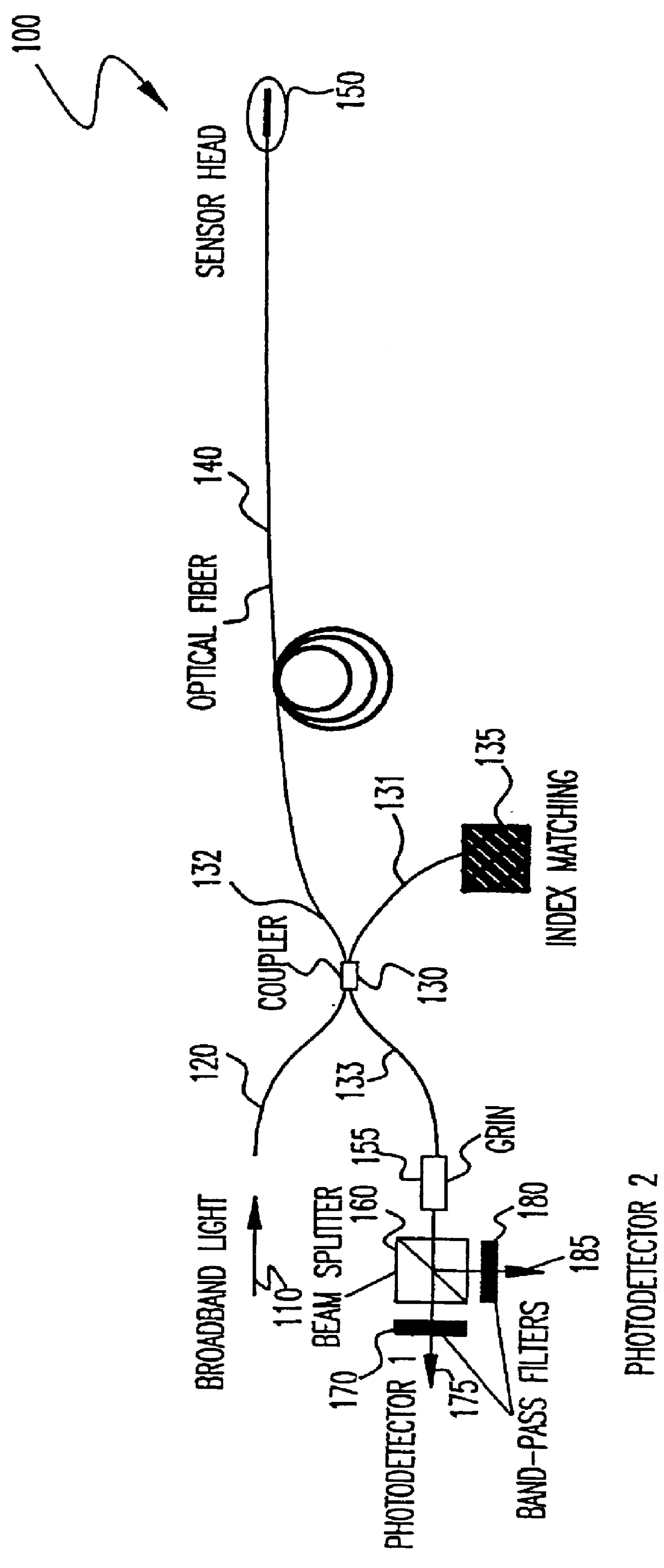
Referring now to the drawings, and more particularly to FIG. 1, there is shown, in schematic form, an optical fiber measurement system 100 in accordance with the invention. It is to be understood that several of the elements shown in FIG. 1 are also common to known optical fiber sensor arrangements (but may not have the same properties as in the present invention) and that the illustration of FIG. 1 is arranged in a manner to facilitate comprehension by those skilled in the art. Therefore, while FIG. 1 may appear similar to some known optical fiber sensor arrangements, no portion of FIG. 1 is admitted to be prior art as to the present invention other than specific elements which may be indicated as possibly being of a known type in the following discussion.

Specifically, the system of the present invention receives energy input from a broadband light source depicted by arrow 110. The precise nature of the broadband light source is not important to the practice of the invention but re...


PUM


Abstract

Broadband energy incident on a transducer having partially or fully reflective surfaces separated by a gap which is greater than the coherence length of the broadband energy but smaller than one-half a coherence length of a band of energy within said broadband energy causes a portion of the spectral content of the broadband energy corresponding to a coherence length greater than twice the gap length to exhibit interference effects while the average power of the broadband energy remains unaffected. Splitting energy reflected from the transducer into two beams which are filtered at preferably similar center frequencies but with different pass bands yields beams which are radically different in sensitivity to changes in gap length. Analyzing the beams to derive a ratio of powers (since source intensity and fiber attenuation in a common fiber are thus self-cancelling) allows high accuracy and high resolution absolute measurement of temperature, pressure or strain. Effects of any of these physical parameters which are not of interest in a measurement can be fully compensated or made arbitrarily insignificant in a simple transducer structure of extremely small size. Use of broadband energy permits measurement over greater lengths of optical fiber.

Description

1. Field of the InventionThe present invention generally relates to remote condition sensors and measurement devices and, more particularly, to remote measurement and sensing using optical fiber communication links.2. Description of the Prior ArtCondition sensing and measurement are encountered in many diverse fields of endeavor. Many of these applications require very precise measurement of a physical parameter and often at extremely inaccessible locations and / or where severe conditions exist. For example, so-called down-hole telemetry in petroleum exploration or production, the sensor may be required to communicate with the remainder of the measurement system over substantial distances while making extremely accurate and highly sensitive measurements of strain, pressure or temperature in an environment of very high temperatures and pressures which may adversely affect calibration of the sensor, compromise accuracy or limit resolution of the measurement through environmental effect...

Claims


Application Information

Patent Timeline
IPC IPC(8): G01D5/26G01K11/00G01K11/32G01L1/24
CPCG01D5/266G01L1/242G01K11/32G01D5/268
Inventor WANG, ANBOZHAO, WEIWANG, JUNXIAO, HAI
Owner VIRGINIA TECH INTPROP INC
Why Eureka
Try Eureka