Time and space efficient data structure and method and apparatus for using the same for surface rendering

Inactive Publication Date: 2000-06-13
INST OF HIGH PERFORMANCE COMPUTING
View PDF2 Cites 46 Cited by
  • Summary
  • Abstract
  • Description
  • Claims
  • Application Information

AI Technical Summary

Problems solved by technology

Providing the seed sometimes is not as easy as one might imagine.
However, it is quite often that this resultant contour is not the one the user wishes to see.
This is obviously computationally intensive.
Without the special mechanism, all cells must be check resulting in time complexity of O(N.sup.3).
The second disadvantage is that the algorithm generates a number of B-faces to patch the object surface.
Compared with other patching techniques such as the triangulation methods known to those skilled in the art, the resultant images can have greater distortions and poorer quality.
Although the algorithm has been generally successful, it has been reported that the 14 rules contain some ambiguity which would result in images with artificial holes.
For example, in a modern computer tomography (CT) and magnetic resonance

Method used


Image

  • Time and space efficient data structure and method and apparatus for using the same for surface rendering
  • Time and space efficient data structure and method and apparatus for using the same for surface rendering
  • Time and space efficient data structure and method and apparatus for using the same for surface rendering

Examples


Example

EXAMPLE 1

t=7.5

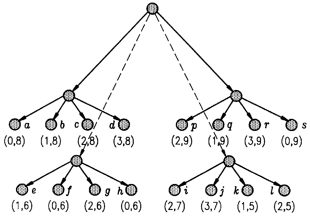
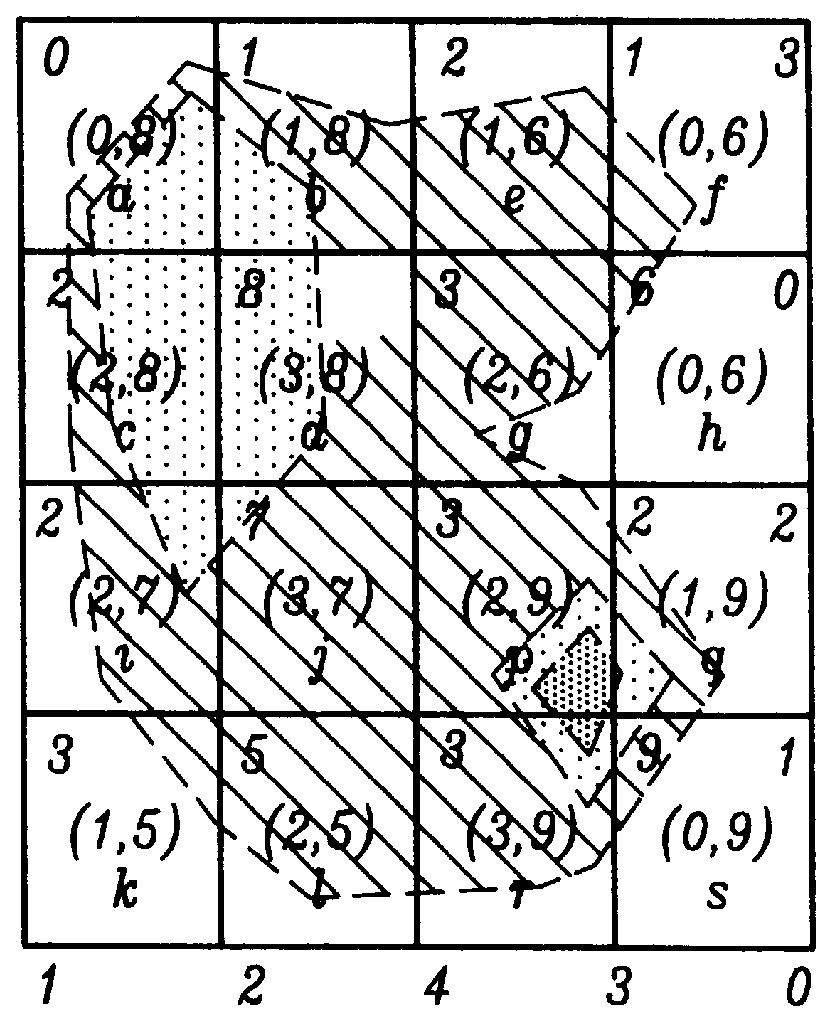
Given t=7.5, the TWSA first visits CL.sub.0 by setting initial index=SIZE.sub.0 =4, and accessing TA(index)=TA(4) which is cell s. Since its (min,max)=(0,9), s is classified as an S-cell. Then the TWSA checks its left neighbor by continuously updating index=index-1 and accessing PA[index], and finds that cell a is an S-cell a and cell h is a 0-cell (because max-field of cell h satisfies max<7.5). So visiting CL.sub.0 will be terminated. There is no need to visit other cells in CL.sub.0 since it is certain that there are no more S-cells in it. Now the TWSA checks CL.sub.1. Similarly, it finds S-cells q and b. In repeating the steps, the TWSA finds all 8 S-cells but it only needs to visit 12 cells.

Example

EXAMPLE 2

t=1.5

Given a threshold t=1.5, the TWSA starts to check CL.sub.0 and then CL.sub.1 and it finds that all cell in CLs: s, a, h, f, q, b, e and k are S-cells. Then it starts to check CL.sub.2. Accessing PA[lndex]=PA[13], it finds cell p, since its min=2>t=1.5, and immediately concludes that there is no more S-cells in the last two CL.sub.2 and CL.sub.3. Thus the whole procedure is completed with checking of only 9 cells, 8 of which are S-cells. Only one cell is of no interest.

2. Comprehensive TWS Data Structure

In the above, it was assumed that the scalar field is evenly distributed. In many situations, however, this assumption might not hold true. For some applications, a scalar field could be digitized as long as 12 bits or more and thus might result in a huge number of CLs. In an extreme case, if each voxel has different density value, then the number of CLs, Q=min(O(N.sup.3), 2.sup.12) would be generated. Directly applying the above data structure might be not practically h...


PUM


Abstract

A computationally time and space efficient data structure and method and system for using the same for surface rendering. The basis for the new data structure lies in organizing a volume data set for surface rendering into a new format where the cells needed for the surface rendering can be searched and displayed more efficiently. Given a threshold t specified by the user, the present data structure is able to efficiently identify all surface cells saving valuable processing time by providing three unique beneficial characteristics. First, given a threshold t, it can directly provide all S-cells without having to check most of the 1-cells and 0-cells such that no time is wasted on visiting the intermediate nodes. Second, it facilitates significant savings in memory space where the data structure only requires N3 pointers for data storage saving memory space for all intermediate nodes, i.e. O(N3) pairs of (Min, Max). And third, it makes viable a searching algorithm which can have parallelization capabilities for finding all S-cells such that the algorithm can be efficiently used in today's workstation employing more than one processor.

Description

The present invention relates generally to three dimensional volume visualization, and particularly to a new data structure and method and system which significantly reduce computational time and space in displaying surface structure of a three dimensional object.Three dimensional volume visualization has been used in various applications such as in medical diagnoses, weather forecasting, molecular design, etc. There are two types of fundamental techniques which can be used for volume visualization: volume rendering and surface rendering. A few popular surface rendering techniques have been developed and extensively used in many interactive applications.With either of these techniques, the fundamental data formation is denoted as volume data depicting a 3-dimensional space scalar field, d=d(x, y, z), which represents a set of values for a certain physical characteristic of a three dimensional object. The volume data is partitioned into N.times.N.times.N identical cubes, called cells...

Claims


Application Information

Patent Timeline
IPC IPC(8): G06T15/00
CPCG06T15/00
Inventor SHU, RENBENLEE, YIH
Owner INST OF HIGH PERFORMANCE COMPUTING
Why Eureka
Try Eureka