

Packaging and applicator device, and a refill element for such a device
- Summary
- Abstract
- Description
- Claims
- Application Information
AI Technical Summary
Benefits of technology
Problems solved by technology
Method used
Image

Examples
first embodiment
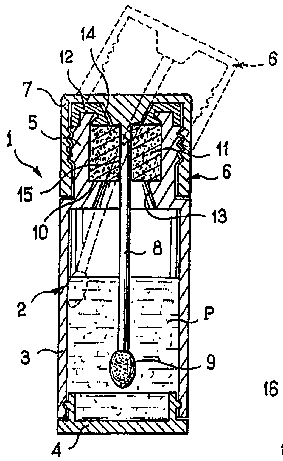
FIG. 1 shows a device 1 of the invention.
The device 1 comprises a receptacle 2 and an applicator 6.
The receptacle 2 is constituted by an injection molded tubular body 3 and a bottom 4 that is snap-fastened to the body 3. The top end of the body 3 has a neck 5 with an outside thread.
In the example described, the receptacle 2 contains a liquid cosmetic P using water as its solvent, e.g. an aqueous formulation of polyurethane or acrylic resin. By way of example, it may be liquid lipstick.
The applicator 6 has a handle member 7 that also serves as a cap for closing the receptacle 2, suitable for being screwed onto the neck 5 and extended downwards by a stalk 8 that can be rigid or flexible, and that is provided at its end with an applicator element 9 that can be of any conventional type, and which is merely represented very diagrammatically in FIG. 1. In the example described, the applicator element has an outside diameter greater than that of the stalk.
By way of example, the stalk 8 has...
fourth embodiment
FIG. 11 shows a device 53 constituting the invention. This device 53 comprises a double-walled receptacle 54 and an applicator 55.
The receptacle 54 is formed by assembling together a lower portion 56 and an upper portion 57.
The lower portion 56 has a central tubular wall 58 that is closed at its bottom end by an add-on bottom 59, and that is extended radially outwards and upwards from its bottom end by an outer skirt 60. The central tubular wall 58 has an inwardly-directed rim 63 at its top end.
The top portion 57 comprises a central tubular wall 61 that is extended outwards and downwards by an outer skirt 62 which is shaped to snap-fasten at its bottom end in the outer skirt 60 so as to obtain a receptacle having a continuous outside surface. The central tubular wall 61 is provided at its top end with an inwardly-directed rim 65.
The wall 58 engages in leakproof manner in the wall 61 and contains the cosmetic to be dispensed.
The rim 63 serves as a support for the bottom end of a bloc...
fifth embodiment
FIG. 12 shows a device 87 constituting the invention.
This device comprises a receptacle 88 and an applicator 89.
The receptacle 88 is formed by assembling together a lower portion 90 and an upper portion 91.
The lower portion 90 has a central tubular wall 92 that is closed at the bottom by an add-on bottom wall 93 and that is extended upwards from its bottom end by an outer skirt 94 that is upwardly concave.
The tubular wall 92 has a shoulder in its top portion and it is terminated by a rim 95 projecting radially inwards.
The top portion 91 of the receptacle 88 comprises a central tubular wall 96 that is extended radially outwards in the vicinity of its top end by an outer skirt 97 which is downwardly rounded with the outer skirt 94 of the lower portion 90 snap-fastening to the inside surface thereof. The tubular central wall 96 then engages in leakproof manner on the top portion of the tubular central wall 92.
A loop 98 integrally molded with the upper portion 91 of the receptacle is hi...
PUM
 Abstract
Description
Claims
Application Information