Foundation soil moisture stabilization system

a soil moisture stabilization and foundation technology, applied in foundation engineering, agriculture, construction, etc., can solve problems such as damage to structures supported on such foundations, damage to foundations, and tilting, cracking and cracking of foundations, so as to prevent stress and damage to foundations, prevent soil overwatering and the associated problems of overwatering

Inactive Publication Date: 2000-07-04
ANDERSON GARY L
View PDF14 Cites 27 Cited by
  • Summary
  • Abstract
  • Description
  • Claims
  • Application Information

AI Technical Summary

Benefits of technology

Thus, the system of the present invention, more accurately controls the moisture content of soil surrounding and beneath the foundation of a building. Water is periodically administered to the soil and the soil is constantly checked for moisture content. When the moisture content exceeds a predetermined amount, signals to open the valve for watering thereof are interrupted, preventing overwatering of the soil and the associated problems of overwatering. In addition, the type of conduits utilized with the present invention allow conduits to be placed in horizontal holes provided therefor directly underneath sidewalks, patios, porches, and the foundation itself, resulting in much more even distribution of water thereto. Thus, the soil surrounding and beneath the foundation of a building is substantially moisture stabilized, preventing stress and damage to the foundation and the supported structure. Many other objects and advantages of the invention will be apparent from reading the description which follows in conjunction with the accompanying drawings.

Problems solved by technology

One can readily see that buildings may be damaged by such expansion and contraction of the soils surrounding and beneath the foundation.
Repeated wetting and drying of the soil, particularly when done unevenly, can place great stress on foundations resulting in tilting, cracking and destruction of the foundation.
This, of course, often results in damage to structures supported on such foundations.
Although such systems may have helped in some cases, they were very inefficient due to lack of uniform distribution of water and the lack of access to soil under driveways, sidewalks and the building foundation itself.
The, soaker hoses utilized with such systems do not evenly distribute moisture without proper flow and pressure controls.
Neither are they capable of distributing the volume of water necessary to correct the supporting soils' loss of moisture.
The low operating pressures allow relatively large flow of water near the point of entry but with volume severely diminished in a short distance.
The hose frequently clogs up due to low operating pressure.
Intrusion of insects, such as ants, typically create problems with such systems.
Although this does improve the distribution of water, such systems also have limitations.
Although such controllers can be pre-programmed for watering cycles of pre-determined length or duration and times between cycles, they often result in overwatering of the supporting soil and cannot compensate for variable moisture content in separate zones or areas of the soil around and beneath the foundation of a building.
If the soil is overwatered, it can cause severe problems.
The soil may actually be liquified, totally destroying its supporting ability.
Overwatering can also cause subterranean erosion in which support soil is actually washed away.
Thus, prior art systems for stabilizing moisture content of soil around and beneath the foundation of a building leave much to be desired.
Although they may operate with limited success, the prior art systems are not uniformly effective and efficient.

Method used


Image

  • Foundation soil moisture stabilization system
  • Foundation soil moisture stabilization system
  • Foundation soil moisture stabilization system

Examples


Embodiment Construction

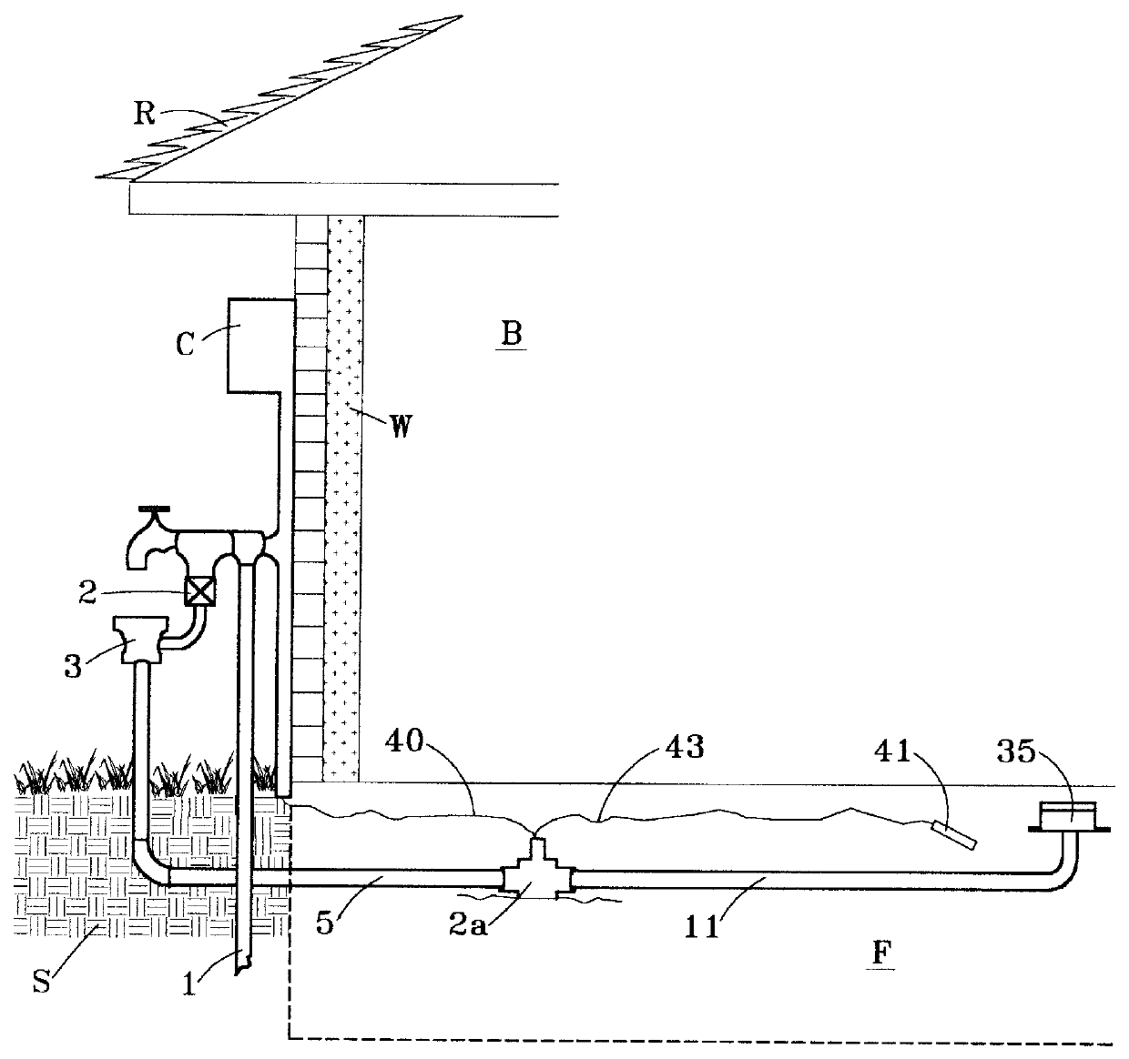
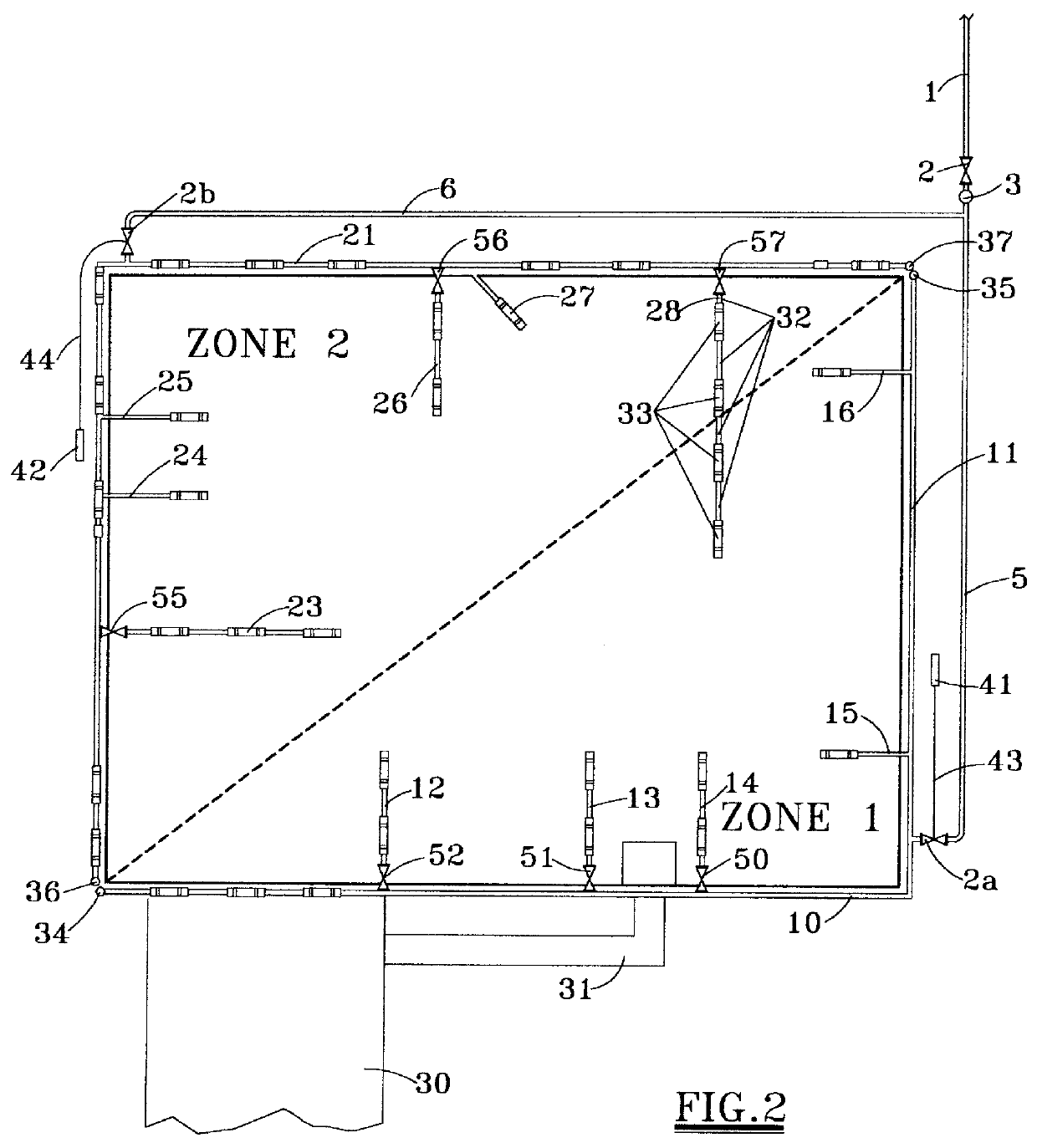
Referring first to FIG. 1, there is shown a building B supported on a foundation F surrounding and beneath which is supporting soil S. The building includes a wall structure W and a supported roof structure R. The building B, for example a house, may have a water pipe 1 from which a source of pressurized water (such as city water) is supplied to the building B. As illustrated in FIG. 1, the water supply pipe 1 is connected through a master valve 2 and a pressure vacuum breaker / back flow preventer 3 to one or more conduits such as the conduits 10, 11, 20, 21, of FIG. 2.

Referring also to FIG. 2, a number of conduits may be supplied from the source of pressurized water in pipe 1 through master valve 2. In FIG. 2, the conduits are actually arranged together in two separate zones or systems, Zone 1 and Zone 2. As best seen in FIG. 2, the conduits lie around the foundation F of the building and in some cases are actually buried beneath the foundation. For example the conduits of Zone 1 in...


PUM


Abstract

A system for stabilizing moisture content of soil around and beneath the foundation of a building. The system includes a source of pressurized water; one or more conduits buried in the soil around the building foundation, at least a portion of soil conduit being pervious to water, allowing water therein to enter said soil; and a remotely operated valve connecting the source of water to the conduits to permit or prevent flow of water, respectively, from the source of water to the conduits. A controller is operatively connected to the remotely operated valve for transmitting signals to the valve for opening and closing thereof in a predetermined time cycle. At least one soil moisture sensitive device is operatively connected to the controller and / or the valve for interrupting signals transmitted to the valve, to prevent opening of the valve when the moisture content of the soil exceeds a predetermined amount.

Description

1. Field of the InventionThe present invention pertains to systems for controlling and stabilizing the moisture content of soil around and beneath the foundation of a building. More specifically, the present invention pertains to an improved soil moisture stabilization system by which water flows to or is prevented from flowing to soil around and beneath the foundation of a building, depending upon measured moisture content thereof.2. Description of the Prior ArtSoils expand and contract to a degree relating to the moisture content therein. Certain types of soil, such as the clay soils of the Gulf Coast, are highly expansive. For example, one dry cubic foot of Beaumont / Lake Charles clay soil can expand up to four cubic feet with the addition of moisture thereto. One can readily see that buildings may be damaged by such expansion and contraction of the soils surrounding and beneath the foundation. Repeated wetting and drying of the soil, particularly when done unevenly, can place gre...

Claims


Application Information

Patent Timeline
Patent Type & Authority Patents(United States)
IPC IPC(8): E02D31/00E02D31/02
CPCE02D31/02
Inventor ANDERSON, GARY L.
Owner ANDERSON GARY L
Why Eureka
Try Eureka