Vehicle-lamp lighting-on device

a technology of vehicle lamps and lighting devices, which is applied in the direction of lighting and heating apparatus, cathode-ray/electron beam tube circuit elements, instruments, etc., can solve the problems of power loss and error operation

Inactive Publication Date: 2000-07-04
NGK SPARK PLUG CO LTD
View PDF15 Cites 42 Cited by
  • Summary
  • Abstract
  • Description
  • Claims
  • Application Information

AI Technical Summary

Problems solved by technology

The conventional vehicle-lamp lighting-on device has the following problems: 1) the number of required component parts is large; 2) mounting of those component parts is troublesome; 3) use of the high voltage cable restricts to design the compon

Method used


Image

  • Vehicle-lamp lighting-on device
  • Vehicle-lamp lighting-on device
  • Vehicle-lamp lighting-on device

Examples


first embodiment

A vehicle-lamp lighting-on device 1 which is an embodiment of the present embodiment will be described with reference to the accompanying drawings.

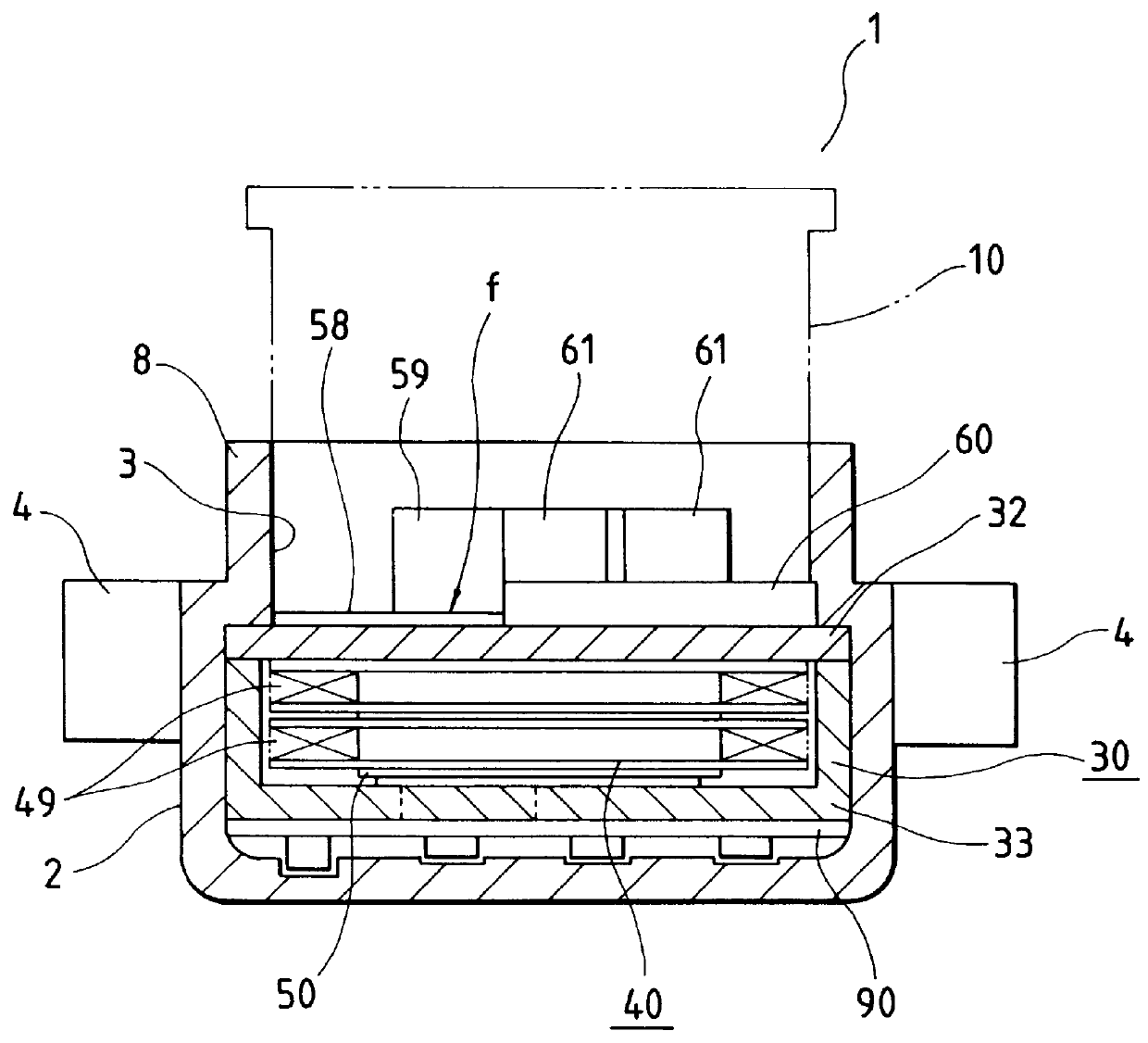
The vehicle-lamp lighting-on device 1, as shown in FIG. 1, is generally made up of a body case 2, a socket 10 and a lighting-on transformer 30, and the like. The body case 2 and the socket 10 are both made of synthetic resin.

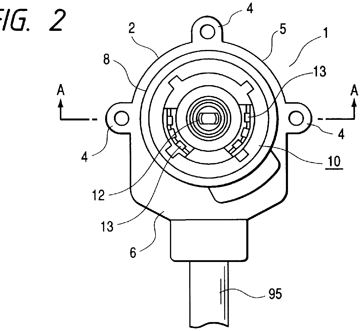
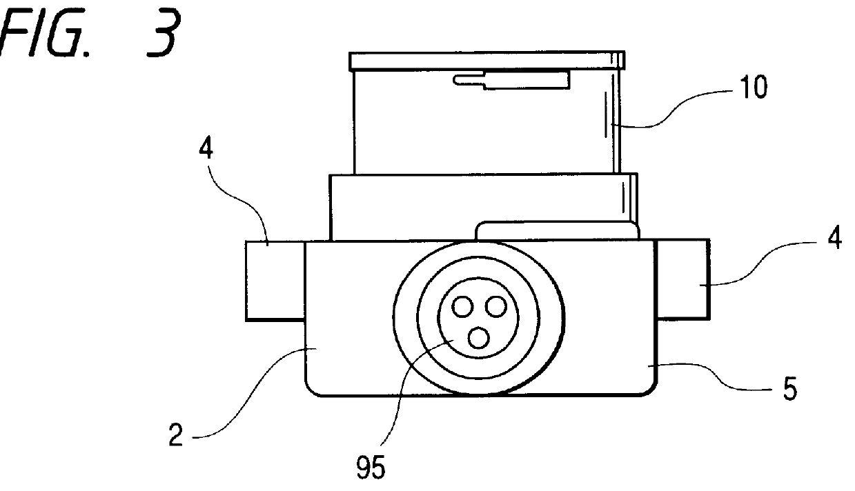
As typically shown in FIG. 2, the synthetic resin body case 2 includes a circular portion 5 and an extended portion 6 extended outwardly of the circular portion 5. The front end of the circular portion 5 is opened to provide a circular connection opening 3 defined by a ring-like circumferential wall 8. A plural number of mounting portions 4 are protruded outward from the circumferential outer surface of the circular portion 5 of the body case 2. The extended portion 6 is somewhat U-shaped when viewed from above. A cylindrical protrusion, which has a through-hole 7 longitudinally formed therein, is protruded outward fr...

second embodiment

A vehicle-lamp lighting-on device 101 which is a second embodiment of the present embodiment will be described with reference to the accompanying drawings.

The vehicle-lamp lighting-on device 101, as shown in FIGS. 13 through 16, is generally made up of a body case 102, a socket 110 and a lighting-on transformer 130, and the like. The body case 102 and the socket 110 are both made of synthetic resin.

As shown, the synthetic resin body case 102 includes a circular portion 105 and an extended portion 106 extended outwardly of the circular portion 105. The front end of the circular portion 105 is opened to provide a circular connection opening 103 defined by a ring-like circumferential wall 108. A plural number of mounting portions 104 protrude outward from the circumferential outer surface of the circular portion 105 of the body case 102. The extended portion 106 is generally U-shaped when viewed from above. A cylindrical protrusion, which has a through-hole 107 longitudinally formed th...

third embodiment

A construction of a vehicle-lamp lighting-on device 200, which is a third embodiment of the present invention, is illustrated in FIGS. 21 and 22. As shown, the vehicle-lamp lighting-on device 200 receives electric power from a power supply Vcc and supplies it to a discharge lamp L to light. Structurally, the vehicle-lamp lighting-on device 200 includes a housing 201 of synthetic resin and a circuit board 202 located in and fastened to a proper location (lower side of 211 in this embodiment) in the housing 201. A socket 203 is attached to an upper part 212 of the housing 201. The circuit board 202 is connected to the power supply Vcc, and various circuit components and circuitry for the secondary current generation are mounted and formed on the circuit board 202.

A transformer 204 is firmly mounted on the circuit board 202. The transformer 204 receives at its primary winding the output current from the primary current generating circuit, and boosts a voltage of the output current to a...


PUM


Abstract

In the vehicle-lamp lighting-on device, a body case has a connection opening formed in the front end thereof. A lighting-on transformer is disposed within the body case. The transformer includes a core housing with an iron core and a coil bobbin with a secondary coil wound thereon. The connection opening of the body case is shielded at the front end of the lighting-on transformer. A socket for receiving a vehicle discharge lamp includes a high-voltage terminal and low-voltage terminals. When the socket is inserted into the connection opening of the body case, the high-voltage terminal of the socket is connected to the high-voltage side terminal of the lighting-on transformer, and the low-voltage terminals are connected to the low-voltage side terminals. The connection opening of the body case is shielded by the front surface (made of insulating material) of the lighting-on transformer. The vehicle-lamp lighting-on device can be completed by merely attaching the socket to the assembly of the lighting-on transformer and the body case. Therefore, the assembly of the device is easy. Further, the height of the vehicle-lamp lighting-on device is reduced overall since there is no need to form a wall corresponding to the shielding member in the body case.

Description

1. Field of the InventionThe present invention relates to a vehicle-lamp lighting-on device for lighting a vehicle lamp e.g., a head lamp, attached thereto.2. Description of the Related ArtA discharge lamp, e.g., a metal halide lamp, is used for a head lamp of a vehicle. The discharge lamp is detachably attached to a socket provided in the front of the vehicle. Electrodes of the discharge lamp are connected to the terminals of the socket. In this example, electric power is supplied from a power source through the socket terminals to the discharge lamp to light the lamp. The power source supplies voltage of about 400V to a lighting-on transformer. The transformer then boosts the voltage and produces a high voltage at the secondary coil thereof, and applies it to the socket terminals. The lighting-on transformer is provided outside the lamp housing having the socket therein. A high voltage cable is led out of the secondary terminal of the transformer, introduced into the lamp housing,...

Claims


Application Information

Patent Timeline
IPC IPC(8): H01F27/00H01F27/40
CPCH01F27/40
Inventor KOHMURA, YOSHIHIKOOSHIMA, TAKAFUMIITO, TOSHIHARUSUGIMOTO, NORIYASUYASUDA, MINORU
Owner NGK SPARK PLUG CO LTD
Why Eureka
Try Eureka