Bicycle brake cable system

a brake cable and bicycle technology, applied in the direction of bicycle brakes, cycle equipment, transportation and packaging, etc., can solve the problems of loss of responsiveness in the brake system, inability to manipulate, and usually quite heavy

Inactive Publication Date: 2000-07-11
BEARCORP
View PDF21 Cites 37 Cited by
  • Summary
  • Abstract
  • Description
  • Claims
  • Application Information

AI Technical Summary

Benefits of technology

One important benefit of repositioning the splitter to incorporate it into the handbrake control is the elimination of the outer splitter housing, since this function is performed by the existing internally threaded passageway that accommodates a threaded barrel adjuster in a conventional bicycle brake adjustment system. The incorporation of the cable splitting function into the brake adjustment mechanism thereby eliminates the requirement for a separate splitter assembly.
A further advantage of incorporating the cable splitting mechanism into the brake adjusting mechanism is the provision of a better cable routing and a smoother, more direct path between the rotor and the brake lever. This results in less lateral flexing of the brake line, less loss of energy in the application of the brake, and less friction in the system.
The brake cable system of the invention makes adjustment of the brake less complicated. The requirement for a separate splitter barrel adjuster is eliminated since the existing bicycle brake lever barrel adjuster performs the required adjustment function. All adjustment is performed at the brake lever assembly located on the handlebar, which is usually accessible and which is not free floating. To the contrary, the necessary adjustments are performed on a structure that is firmly mounted upon the bicycle handlebar, which provides a solid, stationary base for the body of the device.
By repositioning the location at which branches of the brake cable diverge from an intermediate position in the brake cable line to a location at the bicycle handlebars, and by solidly mounting the branching mechanism relative to the handlebars, lateral flexing and energy absorption at the branching location is greatly reduced. This improves the life of the brake cable components and also provides a much greater degree of precision control of braking by the bicycle rider. The present invention involves significantly fewer parts in providing a cable that has branches from a single force application mechanism. As a consequence, the bicycle brake cable of the system of invention is less costly to produce, involves less time to assemble, and reduces both friction and flexure in the brake cable line.
The brake cable system of the invention is beneficial in many ways and results in a savings of maintenance time and money, while being adaptable to various applications. More importantly, however, it accommodates the needs of freestyle riders, and in particular optimizes brake responsiveness.
In the preferred embodiments of the invention the attachment of the core elements of the force transmission cable segments is a direct connection to the single brake lever force application lug. This avoids the necessity and complexity of a second, junction lug of the type utilized in conventional bicycle rotary brake cable systems.

Problems solved by technology

Prior to this time such a manipulation was not possible since the bicycle brake cables extending from the hand brake controls on the handlebars to the brake calipers of the brakes on the front and rear wheels of a bicycle would permit only limited rotation of the steering assembly relative to the frame to an arc of far less than 360 degrees.
Freestyle bicycle components are designed to be very stiff and strong, and are usually quite heavy as well.
The brake cable systems of freestyle bicycles must be free from inordinate flexing, since this leads to a loss of responsiveness in a braking system.
When dragging or flopping occurs, it is difficult for the rider to predict when and where to reach for the grips or pedals before landing.
The reason for this difficulty is that the handlebars may be rotating.
If there is a significant amount of dragging or flopping, the rate of rotation of the handlebars will be affected.
While most of these other variables have been improved adequately by bicycle manufacturers in recent years, flexing and routing problems of the brake cable system have continued to exist.
While attempts have been made to reduce these flexing and routing problems, the systems previously devised have been difficult to adjust, expensive, and bulky.
These prior attempts to improve the responsiveness and reduce flexing in brake cable systems have therefore not gained widespread commercial acceptance.
In a conventional rotatable brake coupling system for exerting tension on a brake mechanism at a plurality of force transmission locations, there are a number of functional problems.
This causes flopping, wobbling, and poor adjustability of the rotor unit at which the forces from the branches of the brake cable are applied.
When the splitter is free to move relative to the handlebars and steering tube of the bicycle, brake modulation is lost.
That is, energy applied to operate the brake lever is lost in pulling the splitter lug, which in turn pulls the splitter in a lateral direction.
Because the splitter is not fixed, fatigue to the cable is created over time by the expenditure of energy just to overcome the friction created by the splitter.
This results from the awkward arcs of the two force transmission cable segments where they leave the rotatable brake coupling rotor and are routed toward the brake lever.
Also, the use of a conventional splitter at an intermediate location in the overall length of the cable makes it difficult to route and tie the cable to the bicycle frame bars without causing odd bends in the cable sheath.
This has the effect of causing poor braking, poor brake modulation, and flopping.
However, the limited number of sizes offered does not effectively address the needs of the user.
Furthermore, post-purchase customization of a bicycle cable in order to make it perform in a way for which it is not designed often negatively affects the braking power.
Braking modulation is lose and cable life is shortened.
Also, because there are so many cables housing, post-purchase length customization of the cable housing is time consuming and makes brake system adjustment difficult.
The various interconnections in the splitter housing produce excessive flexure and friction in the cable system.
This results in greater friction, less brake modulation, and eventual cable failure at the brake lever lug.
Conventional splitter designs also involve manufacturing problems.
The proper fabrication of the splitter housing is therefore both difficult and expensive.
Also, cable assembly of a conventional splitter is very cumbersome and time consuming.

Method used


Image

  • Bicycle brake cable system
  • Bicycle brake cable system
  • Bicycle brake cable system

Examples


Embodiment Construction

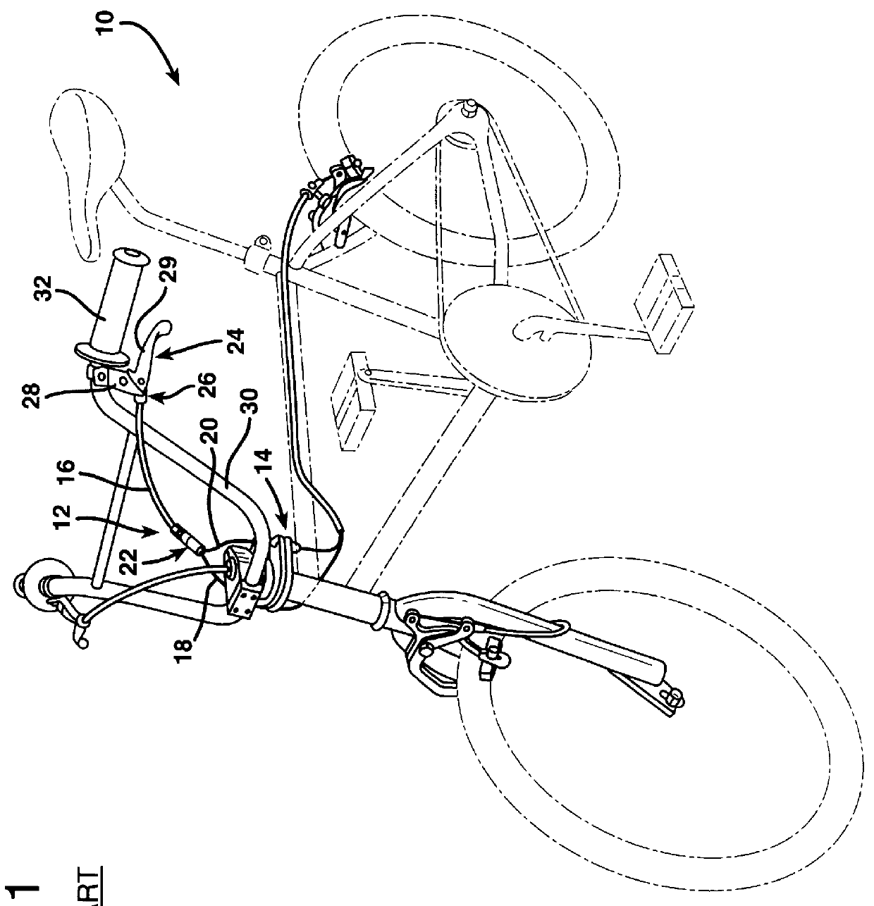
FIG. 1 illustrates a bicycle 10, the standard wheel, sprocket, seat, and frame of which are shown in phantom only as a basis for reference. The bicycle 10 employs a conventional rotary brake cable 12 as employed with a conventional rotatable brake coupling system indicated at 14. The conventional rotary brake cable 12 employs a force application segment 16 to which force transmission segments 18 and 20 are joined at a conventional splitter 22 located at an intermediate location along the overall length of the brake cable 12. In fact, the splitter 22 is typically located rather near the rotatable brake coupling system 14 in conventional systems. The force application end of the force application segment 16 is connected to a bicycle brake lever assembly 24 by means of a conventional barrel adjuster 26. The brake lever assembly 24 includes a brake lever assembly body 28 attached by a mount to the handlebar 30 of the bicycle 10 immediately adjacent one of the handgrips 32 thereof.
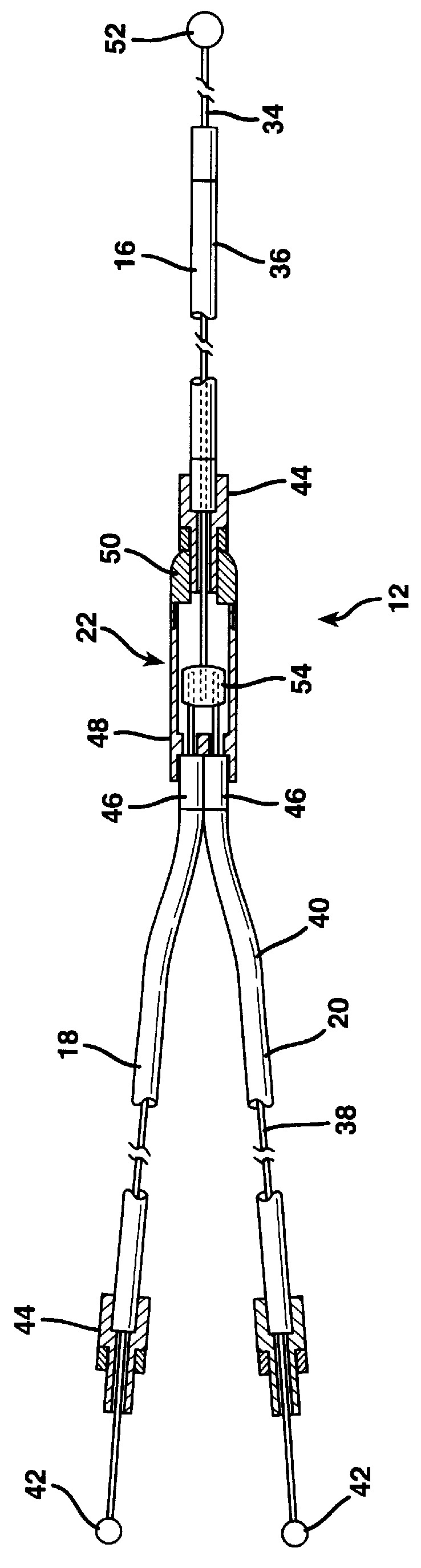
FIG. 2...


PUM


Abstract

A bicycle brake cable system has a brake cable coupling arrangement in which a plurality of branches are provided from a single brake lever force application lug. Splitting of the brake cable is performed within the structure of a brake barrel adjuster. The barrel adjuster is provided with a cylindrical cavity that receives a rotatable coupler therewithin. The interface ends of the force transmission cable segments are terminated in the coupler, which is free to rotate relative to the barrel adjuster. As a consequence, the barrel adjuster may be threadably advanced to either increase or decrease brake tension by rotation relative to its threaded connection to the brake lever assembly body. By providing a coupler that is rotatable relative to the barrel adjuster, the barrel adjuster can be rotated in both directions to increase or reduce brake tension. The relative rotation between the coupler and the threaded nipple of the barrel adjuster allows the force transmission segments of the brake cable to remain stationary relative to the handlebars, while still permitting tension adjustment on the brake cable.

Description

1. Field of the InventionThe present invention relates to a brake cable system in which a bicycle brake cable is split from a single force application lug to a plurality of force transmission locations to apply brakes to the wheel of a bicycle. The bicycle brake cable system has particular applicability to the segment of the bicycle industry known as the freestyle market.2. Description of the Prior ArtA conventional bicycle employs a frame upon which the seat, rear wheel, pedals, and drive transmission mechanism are mounted, and a steering assembly rotatably mounted relative to the frame. The major components of a bicycle steering assembly include a front wheel, a front wheel fork, a steering tube, a handlebar stem, and a set of handlebars. The steering assembly can be turned at an angle relative to the frame about an axis of rotation extending along the center of the steering tube of the steering assembly and the center of the head tube of the frame. The steering tube is mounting c...

Claims


Application Information

Patent Timeline
Patent Type & Authority Patents(United States)
IPC IPC(8): B62L3/02B62L3/08B62L1/00B62L3/00F16C1/26
CPCB62L1/00B62L3/02B62L3/08F16C1/101F16C1/262F16C1/14Y10T74/2045Y10T74/20438Y10T74/2042F16C2326/20
Inventor VALDEZ, ROBERT
Owner BEARCORP
Why Eureka
Try Eureka